Systems of collective reception of satellite television programs
Recently, among our clients, interest in collective reception has noticeably increased. satellite tv. This is due to several objective reasons. Satellite equipment from the category of the exotic goes into a more earthly category of household appliances. If a satellite dish is akin to on-air, then it is logical to assume that it can also be used collectively. Naturally, the cost per viewer (subscriber) should be less than the cost of an individual system. Particularly intensified interest in such systems with the beginning digital broadcasting NTV-Plus and with the expansion of its coverage to the East.
There are many technologies. collective reception satellite channels, each of them has its advantages and disadvantages. The choice of a technology depends on the number of subscribers of the collective network, and on the number of channels to which each subscriber needs to be provided. The purpose of this article is to briefly describe only typical methods for the distribution of satellite channels.
Features of converters for collective reception
These features are due to the fact that satellite broadcasting carried out in different frequency subranges and with different directions of polarization of radiation. Different polarizations are used both in C and Ku - range (vertical and horizontal linear or right-hand and left-hand circular). The width of the C band is only 500 MHz (3.7 - 4.2 GHz) and the entire C - the range is transferred to the input frequency range of the standard receiver (950 - 2150 MHz) by one local oscillator with a frequency of 5.15 GHz. The bandwidth occupied by the Ku band, more than 2 GHz (10.7 - 12.75 GHz), is greater than the width of the input frequency band of the receiver. Therefore, it is impossible to transfer the signal of the entire Ku - range to the receiver's input frequency range by one local oscillator.
For individual reception of signals in different subranges and with different polarizations, as a rule, switchable converters are used. Switching polarization is carried out by changing the voltage of the converter from 13V (vertical, right circular) to 18V (horizontal, left circular). To switch the converter local oscillators, a tone signal (square wave) of 22 kHz with an amplitude of 0.6 V is used, which is added to the supply voltage (no tone — the lower local oscillator is working, F = 9750 MHz, reception in the 10.7 - 11.8 GHz subband; tone there is - the upper local oscillator is working, F = 10,600 MHz, receiving in the 11.55 - 12.65 GHz subband). Such converters are known as Universal. The 13 / 18V and 0/22 kHz control signals come from the receiver via a radio frequency cable.
Switching converters for collective reception cannot be used. Indeed, if the converter is used collectively, and two different subscribers choose channels with different polarization and / or from different sub-bands, a conflict occurs in the system. The converter will switch to the mode corresponding to the priority control signal. The 13V 0 kHz operation mode (vertical polarization, lower subband) has the lowest priority, then the 13V 22 kHz mode, then 18V 0 kHz, and finally, the mode corresponding to the 18 V 22 kHz combination is the highest priority. This means that if such a converter is directly connected to several receivers, and one of the subscribers turned on the upper subband channel with horizontal polarization, the other network subscribers will only be able to receive channels of this polarization and this subband. Of course, this is unacceptable.
In collective reception, a SIMULTANEOUS independent reception of signals with both polarizations and in both subbands should be provided - of course, if such signals are present on the satellite, and if there is a need to receive them. For example, for receiving signals from the Express-6 satellite (80.0 E), the above is not relevant - all channels work with the same polarization — right-hand circular. One converter tuned to receive this polarization can be connected to several receivers via a common power divider (splitter), there will be no conflict. Channels from the GALS satellites, MOST-1 (36.0E) are located only in the upper part of the Ku-band, all of them are processed by one local oscillator, therefore in the collective system it is necessary to ensure the reception of two signals - left-handed and right-handed circular polarization. The most difficult option is receiving Hot Bird satellites (13.0E), Intelsat 707 / THOR (1.0W), where you need to simultaneously receive four signals — both polarizations and both subbands.
For the simultaneous reception, two technical solutions are applied:
Criteria for selecting a collective reception system
For the correct choice of one or another principle of building a system for its future operator (owner), it is necessary to take into account the following characteristics and possibilities:
- The maximum possible number of subscribers.
- Maximum number of satellite channels accessed by each subscriber
- The possibility of partial or full use of the existing distribution network.
- The possibility of using the same equipment for receiving and distributing both satellite and terrestrial channels.
- The possibility of collective reception of digital satellite channels
- System cost per subscriber
- Legal validity of the retransmission of paid channels (NTV-Plus).
Systems with signal distribution in the ranges of MV and UHF - CATV (local cable networks)
Convert FM-AM (Channel Processing)
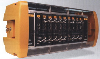
This is a classic principle of distribution of satellite programs. The main difference of such a system from all others is that not only the antenna, but also the receivers are used by subscribers collectively, the subscriber does not have any equipment, except a TV. Satellite head station is used as head equipment. A typical station consists of a mounting housing, a power supply unit, a broadband amplifier unit and a set of channel strips (cassettes). Each channel cassette is an analog satellite receiver and cable modulator. Signal from satellite dish frequency modulated in the range of 950-2050 MHz is received by the receiver and demodulated to audio / video. Then the cable modulator generates a signal in the range of MF or UHF (46 - 862 MHz) with amplitude modulation, i.e. in the same format that is used in on-air and cable tv. The output signals of all channel cassettes are summed up, amplified by a wideband amplifier and fed to the distribution network.
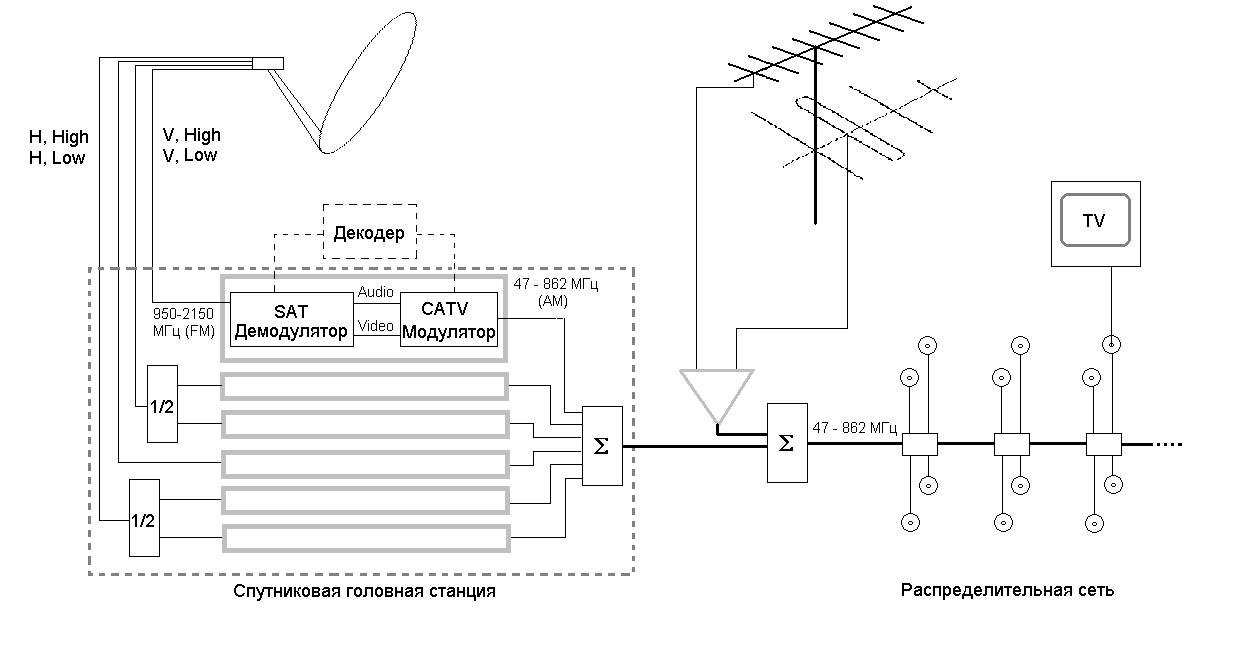
Fig.3 Local layout cable network with analog satellite head station
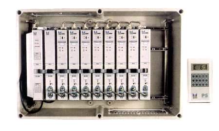
Fig.4 Satellite head station ALCAD ST912 - Appearance
- Theoretically, the maximum number of subscribers of such a system is not limited. Actually it depends on the characteristics of the head station, distribution equipment (cable, amplifiers, passive elements) and the layout of the layout (cable routing, the location of televisions inside buildings, etc.). For example, the head station WISI TOPLINE is able to serve from one entrance (office, hotel, establishment) to a microdistrict.
- The number of satellite channels is limited by the number of station channels - a separate cassette must be installed for each received channel. Practically all satellite head stations assume cascading, - if the capacity of one station is not enough, two, three, etc. stations are installed, their output signals are added together. However, if there are many channels, when choosing a station, it is necessary to pay attention to the quality of modulators. In inexpensive stations, for example, PSM8000 from Pace Microtechnology (UK), simplified modulators are used, without suppressing the lower sideband of the AM spectrum. It is impossible to use such modulators for operation on adjacent channels, the channels must be located at least through one. This circumstance significantly limits the use of such head stations, especially if relaying in the MV band is expected.
- Since satellite channels in the network are no different from the terrestrial, you can use the existing distribution network without any restrictions. Of course, if UHF channels are used, amplifiers and passive network devices should provide operation in the range of 46 - 862 MHz. The old domestic subscriber taps of the UAR-6 and RAF-4, designed only for the meter range (up to 230 MHz), do not meet these requirements.
- In such cable networks, as a rule, satellite and terrestrial channels are simultaneously relayed. If the network is small (one building, part of the building), the signals of terrestrial channels are amplified by channel or band amplifiers (split-band amplification), summed with each other and then with the output signal of the satellite station. In large cable networks, separate channels are used to amplify (and / or convert) terrestrial channels. head equipment. This may be a separate air head station or one universal head station with a set of satellite and terrestrial channel lines. For example, satellite lines OV-53/55 and terrestrial lines OV43 / 45 can be simultaneously installed in the OV-50 installation box of the WISI TOLPINE station. Cable subscriber does not need any equipment other than a TV. Radio and satellite channels are present in the subscriber outlet at the same time, and, from the point of view of the subscriber, do not differ from each other.
- Reception digital channels is carried out in a similar way: at the head station, the channel is received by the digital receiver, decoded to audio / video and transferred by the modulator to the MF (UHF) range. For the subscriber, the digital channel is no different from analog. The digital channel MPEG2 / DVB lines for head stations are still quite expensive. For example, the line of receiver-decoder WISI OV-96 for the TOPLINE station is three times more expensive than the domestic digital terminal. Since the quality of reception in MPEG2 / DVB is determined not so much by the parameters of the equipment as by the broadcast format itself, it is acceptable to use the combination “consumer digital receiver + modulator ruler” instead of the channel bar. As the latter, you can use a modulator analog satellite line. For example, in this way it is possible to use the analog station ST-912 manufactured by ALCAD (Spain) for the collective reception of digital channels. To receive analog channels, the station’s line is fully used; to receive a digital channel, only a modulator is used, to which an external digital receiver (NOKIA DVB9600S or any other) is connected through the standard decoder connector.
- The cost of the head station is much higher than several household receivers in terms of the number of station channels. Therefore, it is advisable to use the described distribution scheme in systems with a large number of subscribers (from several dozen or more) to distribute a small number of channels (from 4 to 20).
Table 1. Systems for collective reception of Express-6 satellite channels
The table shows the cost of the collective reception of 4 channels of the Express-6 satellite using an antenna with a diameter of 180 cm and the Pace PSM8000 head station. For the cost of an individual receiving installation, the cost of a system with the same antenna and a cheap Strong SRT200 analog receiver is adopted.
Table 2. Systems for collective reception of Hot Bird 1-5 satellite channels.
Table 2 shows the cost of the collective reception systems of 8 analog channels of Hot Bird 1-5 satellites using a 3.1 m antenna and the ALCAD ST-912 head station. For the cost of an individual receiving installation, the cost of the system with the same antenna and Strong SRT200 receiver is assumed.
- Retransmission of NTV-Plus programs in the cable network with decoding at the head station is legally unlawful and is punishable by law. As an exception, retransmission in hotel chains and rebroadcasting of foreign production channels included in this package are allowed. In these cases, the conclusion of an agreement with NTV-Plus.
Transmodulation QPSK - QAM
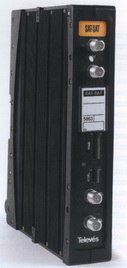
This method is used for collective reception of digital satellite programs. Transmodulators are used as head equipment. In these devices, satellite digital signal with quadrature phase shift keying (QPSK) is demodulated, then the carrier frequency in the range of the MV or UHF is modulated with the received digital stream. For modulation, multipoint quadrature amplitude shift keying (QAM) is used. Thus, a transmodulator converts a satellite digital packet into a cable digital packet. QAM is less protected from interference than QPSK, but more informative - 4, 8 or 16 bits of information for 16-QAM, 64-QAM and 256-QAM respectively are transmitted by a single carrier state (QPSK - only 2 bits). This QAM feature allows you to transfer a satellite digital signal occupying the 36 MHz frequency band into a single television channel band (8 MHz) without reducing the amount of information. In transmodulation, the MPEG2 / DVB transport digital stream is not demultiplexed and not decoded, the entire packet is simply converted from satellite standard DVB-S to DVB-C cable. To receive digital programs Each subscriber must have an MPEG-2 / DVB receiver-decoder with a QAM demodulator. Outwardly, such a receiver looks exactly like a satellite, only instead of the traditional input F-connector, it has an IEC type connector — a conventional antenna connector for connecting to the cable subscriber branch. Structurally, the transmodulator can be made in the form of a standard line for installation in the head-end installation case. For example, the company WISI produces cassettes of transmodulators OV-93/95 for TOPLINE headends. These cassettes can be used in the same station with cassettes of analog satellite receivers and / or modulators. The Spanish firms Televes and Fagor produce head stations of the series consisting only of the transmodulator lines.
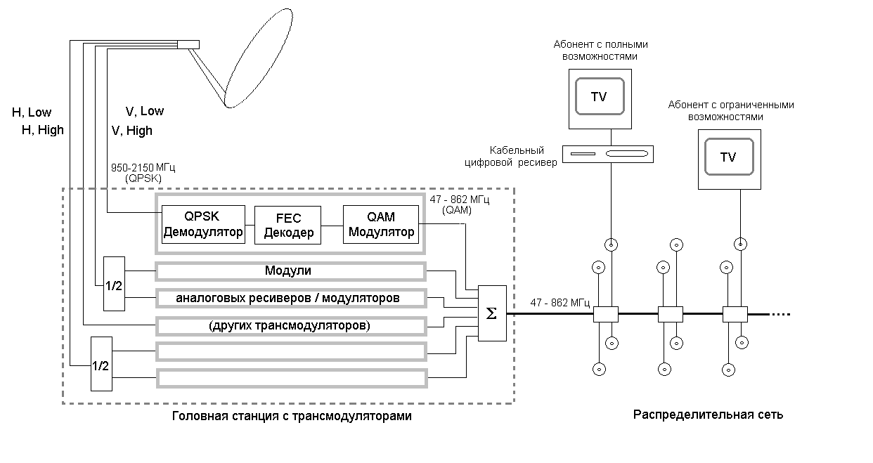
Fig.5 Scheme of the local cable network using QPSK-QAM transmodulators at the head station
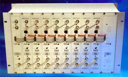
Fig.6 Transmodulator Station Fagor SDT7000 - appearance
- The maximum number of subscribers is theoretically unlimited.
- The maximum number of received channels - depends on the subscriber equipment. If the subscriber has only a TV set, the subscriber gets access only to analog channels on the network. To receive digital programs, the subscriber must have a cable receiver / decoder. Both the receiver and TV are connected to the same subscriber branch, analog channels are received directly, digital ones are decoded by the receiver and output to the subscriber’s TV at a low frequency or radio frequency. Thus, the network operator provides digital channels as an additional service. The subscriber can either purchase (rent) a digital receiver, or be content with receiving only analog channels. Here under analog channels This implies also those digital channels that are decoded at the head station and distributed to the network in analog form (with AM).
- Digital channels with QAM and analog with AM (terrestrial channels and analog satellite channels converted at the head station in AM) are distributed on the network simultaneously without any restrictions.
- The cost of such a system in terms of one subscriber must be differentiated for subscribers with disabilities (TV only) and subscribers with full capabilities (TV + cable digital receiver). For the former, the cost will be determined in the same way as in the case of receiving only analog satellite programs (see Table 1.2). For the second, the cost will be commensurate with the cost of an individual receiving installation. Cable price digital receiver (terminal) at manufacturers approximately the same, as well as the satellite device. However, satellite receivers are purchased by Russian distributors in large quantities, while the demand for cable terminals in our country is almost absent. Of course, when purchasing a small batch of each terminal will cost the buyer much more expensive. Collective reception of digital satellite programs with transmodulation at the head station is economically feasible, if large-diameter antennas are necessary for reception. In this case, the total cost of an individual installation is mainly determined by the cost of the antenna, and there is a direct benefit to use it collectively.
- Collective reception of NTV-Plus digital channels with transmodulation is absolutely legal, since it assumes the presence of a receiver (and therefore an electronic card) for each subscriber. Moreover, NTV-Plus recommends such a distribution method for collective reception. According to unverified data, NTV-Plus CJSC in the near future intends to begin the free sale of the cable version of the digital terminals XSAT CDTV-300 for such networks.
Direct conversion of satellite channels to the MW range
This method is used for distribution of satellite television channels in existing distribution networks, designed only for the range of MV (MF and UHF). Its essence is as follows: a small part of the signal spectrum from the output of the satellite converter without demodulation is transferred by the down converter directly to the MF or UHF range. Such a signal can be distributed in any cable network simultaneously with conventional cable channels. To receive satellite programs, the subscriber must have, in addition to a TV, a subscriber up-converter and a satellite receiver. Such equipment produces, for example, the company WISI. The down converter OV-90 is designed constructively in the form of a standard ruler for installation in the housing of the head station WISI TOPLINE. The converter transfers any part of the 240 MHz width from the LNB output frequency range (950 - 2150 MHz) to the Superband range (230 - 470 MHz, special cable channel range between 12 MB and 21 UHF). Subscriber converter OV-91 is made in a small package for installation on the wall. The OV-91 has one input, which is connected to the subscriber tap of the cable network and two outputs - to connect the TV and satellite receiver, respectively. At the input of the TV signal from the network comes without processing. The converter extracts a signal from the input signal in the 230 - 470 MHz frequency band and converts it into the range of 1000 - 1240 MHz. This signal is fed to the input of a conventional satellite receiver (not cable).
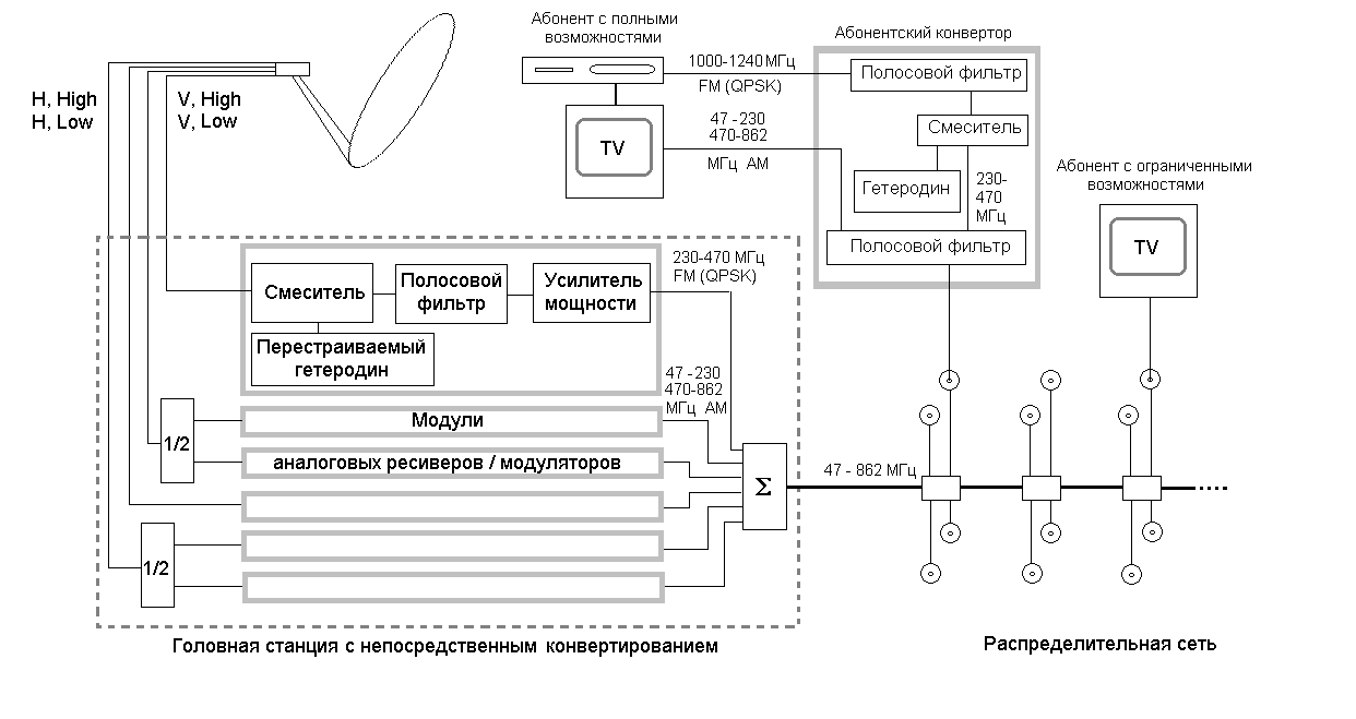
Fig.7 Scheme of a local cable network with direct conversion of satellite channels into the MW range
- The maximum number of subscribers is theoretically unlimited.
- Subscribers of the system with direct conversion are also divided into subscribers with limited capabilities (TV only) and subscribers with full capabilities (subscriber converter and satellite receiver). For subscribers with disabilities, the same restrictions apply to the number of channels that apply to the systems described above. In addition, the signal of a single V-90 converter occupies the entire range of specials. channels in which it would be possible to place up to 30 cable programs with AM. The number of additional channels for subscribers with full capabilities is also limited. First, the system can use only one step-up converter. Secondly, the signal of one satellite program occupies the frequency range from 27 to 36 MHz, and in the entire range of 230 - 470 MHz only 6 to 8 analog satellite channels can be accommodated.
- The existing distribution network can be used without restrictions.
- Satellite channels with FM in the range of 230 - 470 MHz and cable channels with AM in other bands are distributed online simultaneously.
- Theoretically, you can use direct conversion for both analog and digital channels. Of course, in the latter case, the subscriber up-converter should be connected instead of an analog digital satellite receiver. However, since the information in the digital satellite signal is carried by the instantaneous carrier phase, this signal is very sensitive to rapid random changes in the frequency (phase noise) of the local oscillators. Since during the direct conversion, the signal, in addition to the LNB local oscillator, is processed by two other local oscillators - the down converter of the head station and the up-subscriber converter, the total level of phase noise may exceed the allowable level. In this regard, the use of direct conversion for distribution of digital satellite channels is not recommended.
- The cost per subscriber for subscribers with disabilities remains the same as in the two systems described above. For a subscriber with full capabilities, the cost is commensurate with the cost of an individual receiving installation. Therefore, as well as the version with transmodulation of digital channels, it is advisable to use this technology of collective reception for large diameters of receiving antennas.
- The distribution of NTV-Plus channels in networks with direct conversion is absolutely legal. For digital packages NTV-Plus, you must take into account the limitations described above.
Systems with satellite IF signal distribution - SMATV (collective antenna use)
Such systems have the maximum capabilities, but are quite expensive, and, in addition, require partial or full replacement of the distribution network elements. As a rule, such systems are created for a small number of subscribers within the same building.
Systems without frequency multiplexing (Star Distribution)
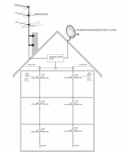
This is the classic version of the collective use of the antenna (s). Since the frequency range of on-air (cable) television (40 - 862) MHz does not coincide with the input frequency range of satellite receivers (950 - 2150 MHz), signals from satellite and terrestrial antennas can be distributed over a single cable. Of course, all passive devices of such a network must operate in the range of 40 - 2150 MHz.
In the simplest case, when signals of one satellite are received in one subband and one polarization (for example, Express-6), the signal from the converter output and output terrestrial antenna (antennas) are simply added up by a bandpass filter (TV-SAT combiner).
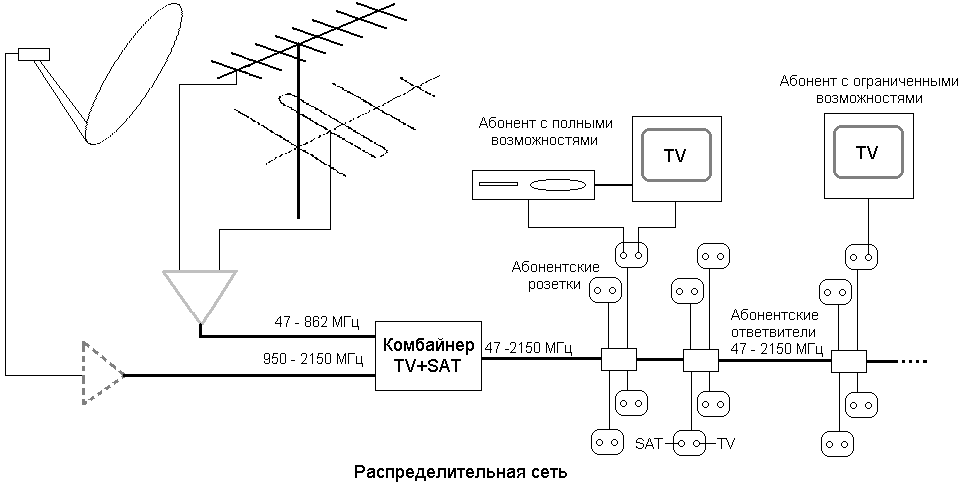
Fig.8. The system of collective channels of the Express-6 satellite and terrestrial channels
The distribution network looks the same as for the distribution of terrestrial or cable programs, only all power dividers (taps and splitters) are designed to work in the range up to 2150 MHz and have a DC bypass - to provide power to the satellite antenna converter subscriber receiver. A special element of the system is the subscriber outlet. The socket for such a hybrid network is equipped with two outputs - to connect a satellite receiver (usually F - connector) and a TV (usually IEC - connector). A range filter is mounted inside the outlet housing that separates the TV and satellite signals. In addition, the output for the satellite receiver has a DC bypass. If the network is small (about 10 subscribers), sockets are also used to divide power between subscribers. For example, the company Televes produces a set of pass-through subscriber sockets # 5417 - # 5419 and a terminal outlet # 5416. In the terminal outlet there is only a band filter, and in the outlet sockets, in addition, directional couplers with different attenuation values for tapping.
Fig.9 Subscriber sockets for collective reception systems of the company Televes (Spain)
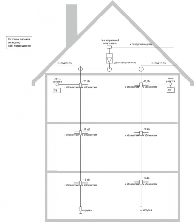
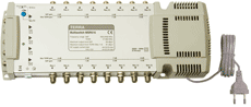
If you need to take satellite signal simultaneously in two polarizations, and / or in two sub-bands, as well as from several satellites, input switches are used for wiring - multiswitches. Such a switch in the simplest case is a matrix switch for N inputs and M subscriber outputs. The number of inputs is 2, 4 or 8 satellite inputs (950 - 2150 MHz) plus 1 input of terrestrial (cable) channels (47 - 862 MHz), the outputs of satellite converters and terrestrial antenna (antenna amplifier) are connected to them, respectively. The number of outputs, as a rule, is 2,4,6 or 8, the ones described above are connected to them subscriber sockets, and to them, in turn, televisions and satellite receivers of the subscriber. The signal from the input 47 - 862 MHz is always present on all subscriber outputs. In addition, each subscriber output It is connected with an electronic key to one of the satellite inputs. To control the electronic key signals are used receiver. For switching two satellite inputs, a 13/18 V polarization switching signal is sufficient.
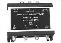
Fig.10 Multiswitch 2 SAT + TV x 4 subscribers - appearance
For the four inputs, the 0/22 kHz subband switching signal is additionally used. For switches with 8 satellite inputs, a 22 kHz signal keying using the mini-DiSEqC (Tone Burst) protocol is used as the third control signal. Thus, each subscriber receiver works as if it is connected to an individual antenna with a switchable converter, or to several such antennas via a mini-DiSEqC switch. For systems with a large number of subscribers, cascaded switches are used. Such switches have N inputs, M subscriber taps and N loop-outs for connecting the next switch. It is convenient to build collective systems in multi-storey buildings on cascaded multiswitches - on each floor, except for the lower one, a walk-through switch is installed, on the lower floor - terminated. Classic multiswitch is a passive device, the signal power from each input is shared passively between all taps by splitters (in terminal multiswitches) or directional taps (in pass multiswitches). If the signal levels at the system input are not enough to compensate for cable attenuation and power dividing losses, active multiswitches are used. These switches are powered by AC power. Usually active multiswitch is placed first (on the top floor), then amplified signal distributed by passive multiswitches. You can get by with only passive devices using external satellite IF amplifiers, for example, Televes # 5082.
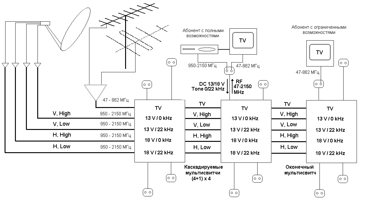
Pic.11 System of collective reception of Hot Bird 1-5 satellite channels and terrestrial channels
- The maximum number of subscribers is small (as a rule, no more than 2 - 3 dozen). This is due to the high cost of equipment and large attenuation of signals in passive devices and cables.
- The maximum number of satellite channels is practically unlimited - each subscriber gets access to all the channels of all the satellites that collective antennas are directed to.
- For systems with distribution in the range of satellite IF elements of the existing air wiring must be replaced. In some cases, you can leave antenna amplifier and subscriber cables.
- Satellite and terrestrial channels are distributed in the system at the same time, although, in principle, you can create two parallel systems - for the distribution of satellite and terrestrial channels. This option is somewhat cheaper, however, it increases the number and total length of subscriber cables.
- Digital and analog satellite channels are distributed in the system exactly the same. Of course, to receive digital channels, the subscriber must have a digital receiver.
- Since the receiver is installed at each subscriber in the system with distribution on the satellite IF, the cost of such a system per subscriber approaches the cost of an individual installation. Economically, the choice of such a system is justified if the number of subscribers is small, if it is necessary to obtain the maximum number of satellite channels and if large-diameter receiving antennas are used.
Table 1. Systems for collective reception of NTV-Plus channels.
The table shows the cost of the collective reception of all NTV-Plus channels using an antenna with a diameter of 90 cm and wiring on multiswitches by SPAUN (Germany). For the cost of an individual receiving installation, the cost of an NTV-Plus branded receiving kit with an antenna of 60 cm was adopted.
Table 2. Systems for collective reception of digital channels of Hot Bird 1-5 and NTV-Plus satellites.
Table 2 shows the cost of the collective reception of digital channels of Hot Bird 1-5 satellites using the antenna with a diameter of 3.1 m and NTV-Plus channels using a 90 cm antenna. For the wiring, SPAUN multiswitches are used. For the cost of an individual receiving installation, the cost of a system with the same antennas, a standard NTV-Plus XSAT CDTV 300 receiver and a DiSEqC 2x1 switch was adopted.
Collective reception of NTV-Plus channels in such systems is absolutely legal.
Systems with frequency sealing of two satellite signals (Single Wire Distribution)
This method of distribution allows you to do without matrix switches, which greatly simplifies the layout of the wiring. However, it is applicable only in some particular cases, namely: if it is required to distribute only two satellite signals (as a rule, a signal of two polarizations of one satellite), occupying no more than 500 MHz in width. This condition is met, for example, by signals from the Bridge-1 satellite (36.0E). The satellite operates with right-handed and left-handed circular polarization and the frequencies of all transponders are located between 12,200 and 12,500 MHz. Compaction occurs as follows: signals of different polarizations are converted to the first intermediate frequency by different local oscillators, as a result, the signal of one polarization is transferred to the lower part of the satellite IF range (950-1450 MHz), the signal of the other polarization - to the upper part (1525-2025 MHz). Then both signals are added by a diplexer filter and distributed over the same cable. As a rule, all the described functional units are structurally performed directly in the body of the satellite converter. A typical example is the Stacked DBS Ku-LNBF 150305 converter manufactured by California Amplifier (USA). This converter is designed for simultaneous reception with compaction of signals of the right and left circular polarization in the range of 12.2 - 12.7 GHz. Signals with right-sided polarization are processed by the local oscillator with a frequency of 11250 MHz and converted to the range of 950-1450 MHz, signals with left-sided polarization of the local oscillator with a frequency of 10675 MHz are transferred to the range of 1525-2025 MHz. The converter has a single output, on which signals of both polarizations are present (950-2025 MHz). For operation in systems with compaction of two polarizations, the California Amplifier releases the subscriber converter DBS Subscriber Unit 150318. This device separates signals from the satellite and television bands, and the satellite signal of the right polarization (950-1450 MHz) is not processed, and the left polarization signal (1525-2025 MHz ) is transferred to the same range of 950 - 1450 MHz using a local oscillator with a frequency of 575 MHz. Inverse transform allows, for example, automatic search for MPEG-2 / DVB channels. If subscribers have receivers installed that do not support automatic search (for example, NTV-Plus receivers), there is no need for reverse conversion. In this case, you can not use the subscriber converters and connect the receivers directly to the subscriber sockets.
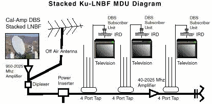
Fig.13 Collective reception system with compressed signals of two polarizations
- The maximum number of subscribers is the same as for PCB wiring without compaction.
- The maximum number of satellite channels is limited by the width of the processed range satellite frequencies - not more than 500 MHz.
- If reverse frequency transfer is not used by the subscriber converter, digital satellite channels are distributed without restrictions. If the subscriber converters are still used, the signals of one of the polarizations are processed by an additional local oscillator, and this increases the phase noise of the entire system. True, the California Amplifier products have a fairly “sharp” phase noise distribution: -90 dBc / Hz @ 100KHz for the satellite converter 150305 and –100 dBc / Hz @ 100 kHz for the subscriber unit 150318, which is quite acceptable for receiving MPEG-2 / DVB channels .
- The cost of the system per subscriber is somewhat lower than the system without compaction, since there is no need to use expensive multiswitches. In addition, the installation of systems with the seal is much easier - instead of several parallel cables laid only one. Therefore, in all cases where the above-described restrictions on the number of channels are permissible, it is advisable to prefer such a system to a system without compression.
Systems with per channel conversion of satellite channels (IF / IF Processing)
Systems with channel satellite converters (processors) combine the advantages of the two systems described above. On the one hand, such systems allow you to collectively receive signals from several satellites in different subranges and with different polarizations, on the other hand, to distribute them over a single cable without using matrix switches. Signals from satellite antennas are fed to the head station, consisting of channel processors (converters). Each channel converter cuts from the output signal of the satellite converter (950 - 2150 MHz) the signal of only one analog channel (digital packet) and transfers it to another carrier frequency in the same range 950 - 2150 MHz. The output signals of the station processors are summed and fed to the distribution network. With the help of several converters, signals from several satellites operating with different polarizations and in different ranges form one satellite signal. Thus, the operator creates his own virtual satellite, on which all the channels of interest to him are concentrated. The signal from one of the satellite converters, which contains the largest number of channels interesting to the operator, is not converted - it is used as the base. Signals from other converters are transferred by channel processors to the “free” frequencies of the base signal. You can also use the “occupied” frequency, for this the gain of the channel processor is increased so that the signal level at the processor output exceeds the level of the base signal on this carrier by 15 - 20 dB.
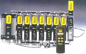
Fig.14 Televes satellite channel processor station - appearance
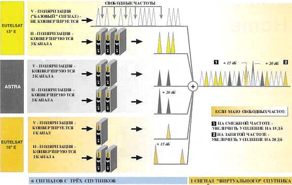
Fig.15 The principle of satellite channel processors
The signal of the "virtual" satellite can be distributed either on the satellite IF (see above "Systems without frequency multiplexing") or in the MV range using a down-converter (see above "Direct conversion of satellite channels into the MV range").
- The maximum number of subscribers of such a system is the same as for PCB wiring without compaction.
- The maximum number of satellite channels is significantly limited, first of all, by the number of channel processors in the headend. However, during channel conversion, the network operator gets the opportunity to include in this number those channels that are most interesting to him.
- Elements of the existing broadcasting should be replaced by elements operating in the frequency range 47-2050 MHz.
- The system assumes distribution of satellite and terrestrial channels through one cable.
- The technical characteristics of channel processors of most manufacturers allow you to distribute both analog and digital satellite channels using the described method.
- On the one hand, the receiver of each subscriber remains, in addition, the head equipment is added, which increases the cost of the system. On the other hand, the distribution network is much simpler, multiswitches are excluded, there is no need to run parallel cables. Therefore, it is economically feasible to use the described system for a relatively large number of subscribers (multi-storey building, hotel). In these cases, the additional costs of channel processors are offset by savings on elements of the distribution network.
Combined systems
Sometimes there is a need to provide the maximum number of programs only to a small group of subscribers, the rest of a rather limited set of channels. A typical example is hotel reception systems. In the suites you need to ensure the reception of all satellite channels, in the other rooms - only the basic package. The optimal solution in such cases is a combination of a system with distribution by MV (UHF) and a system with distribution by satellite IF (using multiswitches or satellite channel converters). Satellite antennas and converters are used simultaneously by both parallel systems. In the "suites" are installed satellite receivers, in the rest of the hotel - only TVs.
For many years I have been using the uncomplicated method of calculating the television subscriber network:
For normal operation of the TV, according to GOST 28324-89, the minimum signal level at its input is 57 dB / µV (0.7mV) in meters and 60dB / µV (1mV) in the decimeter range. In order for these requirements to be fulfilled when two, three or more TVs are connected at the same time, the signal at the input of a divider or a coupler must have a corresponding margin of Ub. Approximately it can be calculated by the formula
Signal margin Udob = k LgN + Pk + Pot
where the k-coefficient takes values from 11 to 20 depends on the loss of the used dividers and couplers.
N is the number of TVs. which is planned to connect
Pc - cable loss.
Pot-pass loss on the coupler (s).
the k-factor takes values from 11 to 20, depending on the loss of the used dividers and couplers. k = P / Lg S, where P is the loss that the used device gives when dividing. S - on how many divides the device. The formula is obtained experimentally.
example: if the divider divides the signal into two with a maximum loss of 3.3 dB (loss at 800 MHz) the ideal divider. k = 3.3 / Lg 2 = 11
if the divider divides the signal into two with a maximum loss of 4.2 dB (loss at a frequency of 800 MHz) is a good divider. k = 4.2 / Lg 2 = 14
if the divider divides the signal into two with a maximum loss of 4.5 dB (loss at a frequency of 800 MHz) of average quality, the divider is k = 4.8 / Lg 2 = 16
and a very bad option, if the divider divides the signal into two with a maximum loss of 6 dB, the bad divider. k = 6 / Lg 2 = 20 (it is better not to use such dividers)
examples: Udob = k LgN + Pk + Pot
Choose medium quality devices as the most affordable k = 15
the length tv cable 15 meters, cable loss 0.18dB per meter (760 MHz)
1. Connect two TVs. The coupler is missing.
Udob = 15 Lg2 + 15x 0.18dB = 4.5 dB + 2.7 dB = 7.2 dB The minimum signal margin is 7.2 dB
The minimum level at the input of the divider is 60 dB + 7.2 dB = 67.2 dB with a subscriber cable length of 15 m.
3. Connecting five televisions. A single coupler is used with a 2dB loss.
Udob = 15 Lg5 + 15x 0.18dB + 2dB = 10dB + 2.7dB = 14.7dB The minimum signal margin is 14.7dB
The minimum level at the inlet of the sender is 60 dB + 14.7 dB = 74.7 dB with a subscriber cable length of 15 m.
By analogy, you can calculate the necessary stock for any distribution network. Calculation must be done several times to select the optimal set of couplers.
example: entrance to a nine-story building, four subscribers per floor.
N = 9 x 4 = 36 36 TVs, the average subscriber cable length is 25m. the distance between the floors is 3 meters of 8 floors x 3 = 24m, the total cable length is 25m + 24m = 49m and the cable loss is 0.15 dB / m, k is chosen equal to 14
The total cable loss is 49m x 0.15dB = 7.36dB / m.
Udob = k LgN + Pk + Pot
Udob = 14 Lg36 + 49x 0.15dB + Pot = 21.7dB + 7.36dB + Pot = 29.06dB + Pot
Without taking into account the transmission loss at the taps, the signal margin should be 29.06 dB. Suppose selected, based on the recommendations (the use of ONT-4-N), taps:
9, 8 floor --ONT-4-24 losses 2 x 1 dB = 2 dB
7, 6, 5 floor - ONT-4-20 loss 3 x 1.2 dB = 3.6 dB
4th floor --ONT-4-17 max. loss = 1.8 dB
3rd floor - ONT-4-14 max. Loss = 2 dB
2nd floor - ONT-4-12 max. Loss = 3.2 dB
1st floor - ONT-4-10 or ST-1/4
2dB + 3.6 dB + 1.8 dB + 2dB + 3.2 dB = 12.6 dB
Udob = 29,06dB + 12,6dB = 41.66dB
The minimum level at the input of the distribution network is 60dB + 41.66dB = 101.66dB. Practically, using a cable with less losses, this level can be reduced by several dB
According to GOST 52023-2003 cable television system: A system that includes technical means and cable communication lines that provide communication services (television, broadcasting, other telecommunications).
It is designed for bidirectional or unidirectional transmission of radio signals from television, radio broadcasting, and other telecommunication signals between the source and the receiver. Standard transmission frequencies of television channels in home networks based on coaxial cables: 47-862 MHz, they form an uplink channel. Frequencies below 47 MHz are used for control functions - content selection, messaging, etc., they form a downlink channel.
Cable television systems consist of three main parts:
- Source television signals . In this case, it is not the primary source (television studio) that is meant, but a secondary one, for example, an antenna or cable television input;
- Head station - a device that converts the incoming signal into a signal transmitted through the distribution network;
- Distribution network - a network of signal transmission from the head station to receiving devices; classic - built on the basis of coaxial cable, more modern systems use the IP network infrastructure, including wireless wifi channels.
Its benefits include:
- Low cost per point of connection - the same service, received individually, will cost much more;
- High quality signal reception - for a properly designed network;
- Affordable service - also due to the number of connection points;
- Preserving the appearance of the building, does not require the installation of a large number of individual antennas;
- The absence of additional cables stretched from antennas to receivers;
- The ability to quickly upgrade the system as a whole.
Scheme for apartment buildings
Since Cable television systems (CATV) are collective systems with a large number of subscribers, they are most widely used in the construction of apartment buildings. The main station, consisting of a base unit (chassis) and a set of functional modules, connects signals from the source, which can be cable channels, terrestrial or satellite antennas. As a rule, the function of the headend is limited to simply amplifying the incoming channels. The incoming signal through the distribution network is distributed along the main access channels, and on each floor it branches into the required number of subscribers, while its quality does not deteriorate due to the use of amplifiers.
To create a collective reception system digital television a slightly more complicated scheme is used. Now the functions of the headend are not limited to gain. Satellite signals are demodulated, while paid channels, coded programs are decoded and transmitted to a common network. Since Since the cable operator has the ability to create its own digital packets, they are often re-encoded, but already with the cable operator’s own coding system, which gives him the opportunity to control subscribers' access to programs and collect pay-per-view. Then the digital streams are sent to the distribution network.
Depending on the model of the head station, it can form a signal into a standard analog coaxial network, into a digital coaxial network, into a digital IP network. Or in several types of networks at the same time.
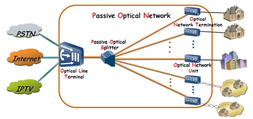
Currently, PON technology, which uses passive optical networks (Passive Optical Network) for signal transmission, is becoming widely used.
The PON network is based on the use of only one transceiver, from which information arrives at the subscriber devices and is received from them. The number of subscriber devices depends on the power and maximum speed of the transceiver device. The scheme of work is based on the fact that a passive optical network of a tree structure is created between the central node and the consumer nodes. In the nodes of the network are optical splitters that do not require power and maintenance. Organized direct data transfer operator-subscriber.
The “trick” of the PON technology is that on one channel, the subscriber receives three streams of digital data - telephony, Internet and television. At the same time, the network operator has the opportunity to get three different subscribers in the person of one, but at the same time he has the ability and reduce the total cost of services.
Scheme with head station and distribution over coaxial cable
Traditionally, cable television systems are collective reception systems with a large number of subscribers, their scale can be from a block of apartment buildings built by cable operators on the basis of coaxial cable to provide cable TV services to the public. The previously installed systems still continue to work at many sites, although the operators gradually replace them with more modern ones.
The cable television system (CATV) consists of three parts: signal sources, head station, distribution network. With such a scheme of work, the “trunk” wiring is performed with a single cable, and instead of expensive and complex matrix switches, compact and cheap dividers are used, so the system is inexpensive and easy to install.
Signal distribution schemes for IP networks. IPTV
This is the most modern technology used today to create a collective television reception system.
In IPTV systems, television programs are delivered to subscribers via computer networks using the Internet Protocol (IP). Broadcasting is localized in the cable network of one operator - as a rule, it is an Ethernet or ADSL network. This network uses various mechanisms to guarantee the quality of video delivery. To view the programs used by the TV, which connects to a computer network through a special console.
Hybrid systems
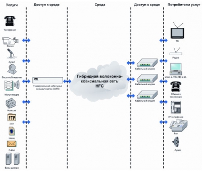
A hybrid network is a network consisting of copper and fiber optic backbone cables. The central head station connects fiber-optic communication lines with several local head stations, which, through their own optical nodes, serve local optical-coaxial networks, each of which covers from tens to several thousand subscribers.
The principle of building such networks is based on the fact that the widest and longest backbones are built on fiber optic cables, and networks in homes are built on coaxial cables or twisted pair.
The main topology of the construction of hybrid networks:
- FTTC. Fiber To Carb (optics to a group of houses);
- FTTB. Fiber To Buildin (optics to buildings, buildings);
- FTTH. Fiber To Home (optics to the house or apartment (PON)).
The name of the technology displays the balance between the optical and copper components of the hybrid network. In FTTC networks, coaxial cable technologies make up the largest part, and optical ones - the smallest. FTTH networks, on the contrary, contain in their structure a minimum of coaxial technologies or do not contain them at all. It is this technology (it is better known as PON) that most fully meets modern requirements, since allows you to transfer the largest flow of information to the subscriber through the physical environment.
Development of cable television systems
The development of SKTV systems includes standard steps:
- Identify customer needs and key requirements;
- Inspection of the object to determine the location of the equipment;
- Development and coordination of technical specifications with the customer;
- Development and coordination of major design decisions;
- Expertise;
- Development of the stage "Working documentation";
- Development of budget documentation;
After that, the system is implemented.
Collective - is called reception, when the signal from one (or several) antennas is distributed to several subscriber satellite receivers (receivers). There is no need to install an individual antenna for each subscriber. It often happens when the local house management or homeowners association prohibits the installation of satellite dishes on the facade of the building, and there is simply not enough room on the roof for everyone.
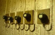
And sometimes there are such heaps of satellite dishes:
The use of a single antenna for all tenants is a way out of this situation. On some satellites, a sufficiently large antenna size is required, which can be difficult to install outside the window. Installing such an antenna on the roof and connecting several subscribers to it will save both money and getting the desired channels.
Even in one house in the conditions of urban development, it often happens that the desired satellite is visible from a neighbor, and you no longer have it. A collective reception system will help solve all these problems.
There are many technologies for the collective reception of satellite channels, each of them has its advantages and disadvantages. The choice of a technology depends on the number of subscribers of the collective network, the number of channels to which each subscriber needs to be provided, and the type cabling (either existing or newly created). This article describes the main methods of collective reception of satellite television.
Options for collective reception of satellite TV:
Option 1. The distribution of the signal for 2-8 subscribers.
The focus of the antenna is not an ordinary converter with one output, but a converter with 2, 4, or 8th INDEPENDENT outputs. Separate cable is laid from each satellite to each subscriber. Each subscriber will work as if he is connected to an individual antenna.
The increase in the number of subscribers in this scheme is possible due to the installation of an additional antenna, as well as through the use of multiswitches.
Option 2. The distribution of the signal for 8 or more subscribers.
In this case, depending on the selected satellite, special converters are used. The signal from them is fed to a special device - multiswitch. Multiswitch has several satellite INPUTS and some number of outputs (4, 8, 12, 16) from which the signal is transmitted to subscribers. A separate cable is laid from the multiswitch to each subscriber. For each subscriber, everything will work as if it is connected to an individual antenna. Also multiswitches can be cascaded and thereby increase the number of subscribers.
Satellite receivers with support are used as satellite receivers dVB-S standard.
The main components for building a collective satellite TV system based on multiswitches:
- 4x4 and 4x8 cascaded multiswitches
- Radial multiswitches from 4 to 32 outputs
- Head and line amplifiers (4-cable system)
- Line amplifier
Option 3. Transmodulation QPSK - QAM based on head-end stations.
This method is used for collective reception of digital satellite programs. Transmodulators are used as head equipment. With transmodulation, the MPEG-2 / DVB transport digital stream is not demultiplexed and not decoded, the entire packet is simply converted from the DVB-S satellite standard to cable DVB-C. To receive digital programs, each subscriber must have an MPEG-2 / DVB receiver / decoder with a QAM (digital cable receiver) demodulator. Outwardly, such a receiver looks exactly like a satellite, only instead of the traditional input F-connector, it has an IEC type connector — a conventional antenna connector for connecting to the cable subscriber branch.
Satellite receivers with support are used as satellite receivers dVB-C standard (cable).
Option 4. Channel conversion of satellite channels (IF / IF Processing) based on head-end stations.
Such systems allow you to collectively receive signals from several satellites in different subranges and with different polarizations, and distribute them over a single cable without using multiswitches. Signals from satellite antennas are fed to the head station, consisting of channel processors (converters).
Each channel converter cuts a signal of only one digital packet from the output signal of the satellite converter (950-2150 MHz) and transfers it to another carrier frequency in the same range 950-2150 MHz.
The output signals of the station processors are summed and fed to the distribution network. With the help of several converters, signals from several satellites operating with different polarizations and in different ranges form one satellite signal. Thus, the operator creates his own virtual satellite, on which all the channels of interest to him are concentrated. The signal from one of the satellite converters, which contains the largest number of channels interesting to the operator, is not converted - it is used as the base. Signals from other converters are transferred by channel processors to the free frequencies of the base signal.
Satellite receivers with DVB-S standard support are used as satellite receivers.
Option 5. Convert FM-AM (Channel Processing) based on head-end stations.
This is a classic principle of distribution of satellite programs. The main difference of such a system from all the others is that not only the antenna, but also the receivers are used by subscribers collectively, the subscriber does not have any equipment, except for a TV. Satellite head station is used as head equipment. Each channel cassette is a satellite receiver and cable modulator. The signal from the satellite antenna with frequency modulation in the range of 950 - 2150 MHz is received by the receiver and demodulated to audio / video. Then the cable modulator generates a signal in the range of MF or UHF (46 - 862 MHz) with amplitude modulation, that is, in the same format that is used in terrestrial and cable television. The output signals of all channel cassettes are summed up, amplified by a wideband amplifier and fed to the distribution network.
In the simplest case, this option is built on the basis of satellite receivers, each of which provides one channel, which are summed and fed into the distribution network. The number of channels depends on the number of receivers.
If the number of subscribers is not large, then the best option (for the price and number of channels) will be building a multiple access system using converters (for several outputs) or multiswitches.
If it is necessary to distribute the satellite signal to a large number of abenents (a multi-storey building or a hotel), then the most optimal would be to build a collective viewing system based on the head stations according to the principle of channel-by-channel satellite conversion (IF / IF Processing).
Advantages of IF / IF Processing:
- The possibility of using the existing cabling (it is necessary to replace dividers and taps for signal transmission in the range of 46 - 2150 MHz)
- The ability to receive all Tricolor channels (45 channels) and NTV Plus (100 channels), as well as other satellite TV operators from one cable by all subscribers independently of each other (the only difference is in receivers and smart cards for paid packages)
- You can install multiple receivers for each subscriber without laying additional cables (for example, from the switchboard to the apartment)
- As receivers, conventional satellite receivers of the DVB-S standard are used, which the subscriber can purchase independently.
- The broadcaster’s copyright is not violated, as the signal from the satellite is transmitted to the network (and not the decoded channel), and the subscriber pays for viewing by purchasing a receiver with a smart card (for example, Tricolor, NTV Plus, Orion )
- The integration of the video surveillance system into the collective viewing system of satellite TV is possible.
Methods and means of transmitting a television signal
For the first time, the moving image was transmitted at a distance on July 26, 1928 in Tashkent by the inventors Grabovsky and Belyansky. Although the images obtained were rough and unclear, it is the Tashkent experience that can be considered the birth of modern television. The first television receiver in history on which this experiment was conducted was called the “telephoto”.
In the 1930s, the development of television was conducted in the USA and Germany. For the first time a live broadcast was tested at the 1936 Olympiad in Germany. In the USSR, the most experienced television broadcast session was held on April 29, 1931. In 1937, the first television center was organized on Shabolovka Street, which in 1938 carried out experimental television broadcasting on the basis of electronic systems, and since 1939, permanent television broadcasting (the first program was a film about the opening of the 18th Congress of the CPSU (B)).
Thus, more than 80 years have passed since the moment when a person for the first time managed to transmit a moving picture over a distance through a radio signal. Since then, television technology has stepped so far ahead that it becomes more difficult to trace their connection with the good old “box” connected to a common antenna. Currently, there are different ways of delivering television content to the consumer: by transmitting a signal over the air using ground stations (NS), via artificial earth satellites (AES), and through cable TV systems.
Air television
Satellite television
Cable TV
The system of collective reception of television (SCCT)
Purpose of SKPT
The system of collective television reception (SCTC) is intended for the reception of terrestrial, satellite, cable television programs and their broadcast on the building's cable distribution network. (CCST) provides the ability for each subscriber to watch television programs broadcast from terrestrial transmitting centers, from artificial earth satellites (AES) and cable operators.