DIY repair of a hair dryer.
We are all familiar with such an auxiliary tool in construction as a construction electric hair dryer, which we are used to using for removing paint and varnish coatings.
The fundamental principle of operation of a construction hair dryer is not much different from an ordinary hair dryer that we use to dry our hair.
Accordingly, the electrical circuit of a building hair dryer is similar to the electrical circuit of an ordinary hair dryer.
An explanation will be given in the stated topic:
- the electrical circuit of the building hair dryer;
- the principle of the construction hair dryer;
- possible reasons for the malfunction;
- elimination of these malfunctions.
Electrical diagram of a hair dryer
Consider the electrical circuit \ Fig. 1 \ of the building hair dryer:
One diagonal of the diode bridge is connected to an external source of alternating voltage 220V.
The other diagonal of the diode bridge is connected to the electric motor.
The electrical diagram consists of the following elements:
- toggle switch performing the control temperature mode - K1;
- a toggle switch that controls the speed of rotation of the rotor of the electric motor \ control the speed of blowing \ - K2;
- toggle switch for disconnecting heating elements - K3;
- electric motor \ fan \ - M;
- capacitor - C;
- Heating elements - R \ heating elements \;
- diodes - VD1, VD2.
Through the diode bridge circuit \ one diagonal of the bridge \, the rectified current of two potentials \ +, - \ is supplied to the electric motor. When passing from the anode to the cathode, the current flows with a positive half-cycle of the sinusoidal voltage.
Two capacitors connected in parallel in an electric circuit serve as additional smoothing filters.
The blowing speed occurs due to the variability of the resistance in the electrical circuit, that is, when the speed toggle switch is switched to the highest resistance value, the rotation speed of the electric motor rotor decreases \ due to the voltage drop \.
The number of heating elements \ heaters \ in this scheme is four. The temperature regime of the construction hair dryer is carried out by the temperature control toggle switch.
The heating elements in the electric circuit have different resistance, - accordingly, the heating temperature when switching from one section of the electrical circuit to another - heating the heating elements will correspond to its resistance value.
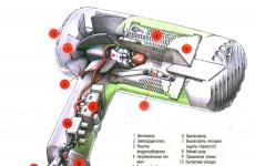
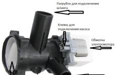
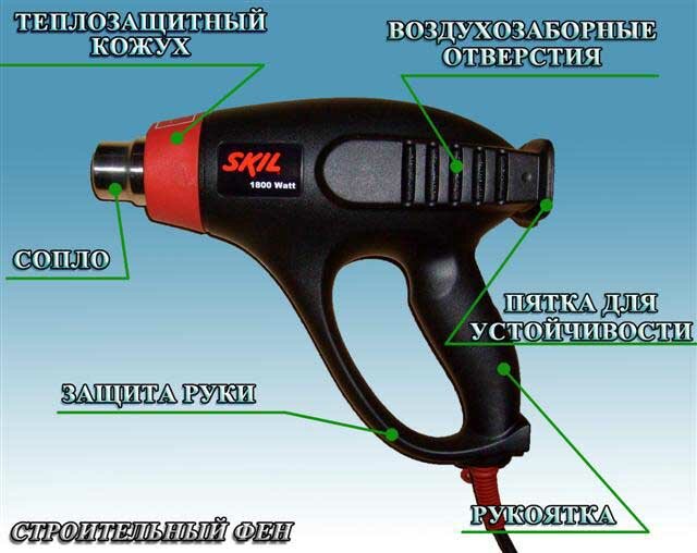
The general appearance of the construction hair dryer with its names of individual parts is shown in Fig. 2
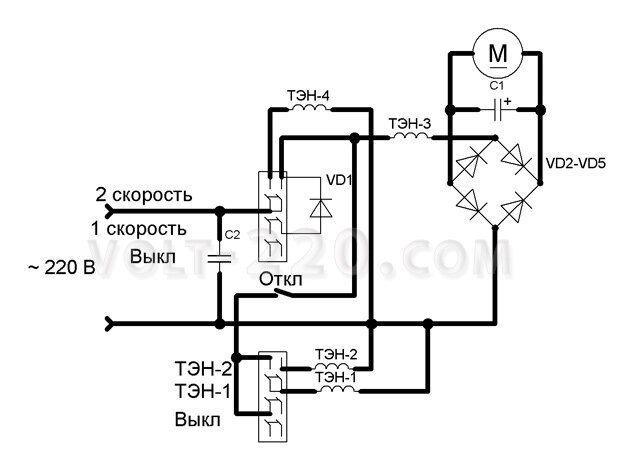
The following electrical diagram of the building hair dryer \ Fig. 3 \, - is comparable to the electrical circuit of Fig. 1
There is no diode bridge in this wiring diagram. Blowing speed control and temperature control - occurs when switching from one section of the electrical circuit to another, namely:
- when switching to a section of an electrical circuit - consisting of a diode;
- when switching to a section of an electrical circuit that does not have a diode.
When a current flows in the anode-cathode junction of the diode VD1, which has its own resistance, the heating element2 will heat up according to two resistance values:
- resistance at the transition anode - cathode diode VD1;
- resistance of heating element \ heating element2 \.
When a current flows in the anode-cathode junction of the diode VD2, the voltage supplied to the electric motor and the heating element1 will take the lowest value.
Accordingly, the speed of rotation of the rotor of the electric motor and the heating temperature of the heating element for a given section of the electric circuit will correspond to the direct transition of the current of the diode VD2. Heating of the heating element \ heating element1 \ for a given section also depends on its internal resistance, that is, the resistance of the heating element is taken into account.
Faults in the construction hair dryer
The main reasons for the malfunction of the construction hair dryer here can be called the malfunction of the electronics elements:
- diodes;
- capacitors.
Most often, such a malfunction occurs with a sharp jump in an external source of alternating voltage. For example, the cause of a capacitor malfunction is caused by the fact that the capacitor plates are closed when there is a voltage jump between themselves - short-circuited.
Of course, such a possibility of a malfunction as a rupture in the stator winding of an electric motor \\ winding burnout \\ is not excluded.
Minor malfunctions include such reasons as:
- oxidation of the temperature control toggle switch contacts;
- oxidation of the contacts of the toggle switch for controlling the blowing speed;
- oxidation of the contacts of the toggle switch for disconnecting the heating elements;
- a wire break in a network cable;
- malfunction of the plug \ lack of contact \.
Diagnostics to identify the cause of the malfunction is carried out by the "Multimeter" device.
When replacing a capacitor, its capacity and voltage rating are taken into account.
When replacing a diode, the resistance of two values is taken into account, in the directions:
- from anode to cathode;
- from the cathode to the anode.
As we know, the value of resistance from anode to cathode will be significantly less than from cathode to anode.
With an electric motor, in case of its malfunction, things are more complicated. With such a malfunction, it is easier to replace the electric motor than it is permissible to rewind the stator windings. But even such work is doable - who is directly involved in such repairs. In this case, the following is taken into account:
- the number of turns in the stator winding;
- section of copper wire.
Such a malfunction as burnout of the heating element is not excluded. Replacing the heating element is carried out taking into account its resistance value.
Diagnostics and repair-building hair dryer
Consider the device of electric motors and how exactly it is necessary to diagnose electrical machines, as they are usually considered in the section on electrical engineering.
For an illustrative example, photographs of several types of such electric machines are presented - related to collector motors. The device and principle of operation are admissible two collector electric motors:
- vacuum cleaner;
- construction hair dryer,
- is no different. The difference in electric motors is only in the rotor speed and in the power of the electric motor. Therefore, we, as it were, will not focus our attention in the sense that explanations are given that are not related to the electric motor of the construction hair dryer.
Electric motor for a hair dryer
The electric motor of the building hair dryer is asynchronous, collector, single-phase alternating current.
asynchronous collector motor single-phase alternating current
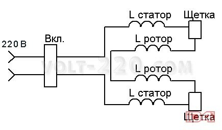
The electrical diagram of the collector motor \ Fig. 5 \ is as follows:
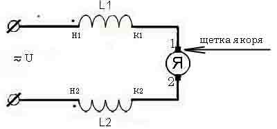
In the circuit, we can notice that the collector motor can operate on both alternating and direct current - these are the laws of physics.
The two stator windings of the electric motor are connected in series. Two graphite brushes in contact - in electrical connection with the motor rotor collector.
The electrical circuit is closed on the rotor windings, - accordingly, the rotor windings in the electrical circuit are connected in parallel through the brush-collector sliding contact.
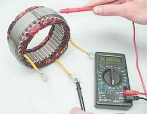
diagnostics of stator windings of an electric motor
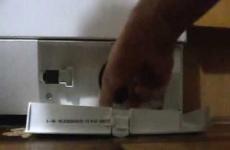
The photograph shows one of the ways to diagnose the stator windings of an electric motor. In this way, the integrity or breakdown of the insulation of the stator windings is checked. That is, one probe of the device is connected to any of the removed ends of the stator windings, the other probe of the device is connected to the stator core.
In the event that the stator winding insulation is broken and the winding wiring shorts to the core, the device will indicate a short circuit mode \ zero resistance value \. It follows from this that the stator winding is defective.
The device in the photograph indicates a one when diagnosing - this does not mean that this stator winding is suitable for operation.
It is also necessary to measure the resistance of the windings themselves. Diagnostics is carried out in the same way in a similar way, - the probes of the device are connected to the removed ends of the stator winding wires. With the integrity of the windings, the display of the device will indicate the resistance value possessed by this or that winding. If one or another stator winding breaks, the device will show "one". If the stator winding wires are short-circuited to each other as a result of overheating of the electric motor or for other other reasons, the device will indicate the lowest \ zero \ resistance value or "short circuit mode".
How to check the resistance of the rotor winding with a device? - To do this, you need to connect two test leads of the device to two opposite sides of the collector, that is, you need to make the same connection that graphite brushes have in electrical connection with the collector. The diagnostic results are reduced to the same indications as when diagnosing the stator windings.
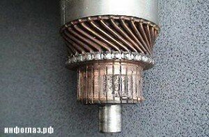
collector plate wear
What is a collector in general? - The collector is a hollow cylinder consisting of small copper plates of a special alloy, isolated from each other and from the rotor shaft.
In the event that the damage to the collector plates is insignificant, the collector plates are cleaned with fine-grained emery paper. Again, this amount of work can be performed directly only by specialists who repair electric motors.
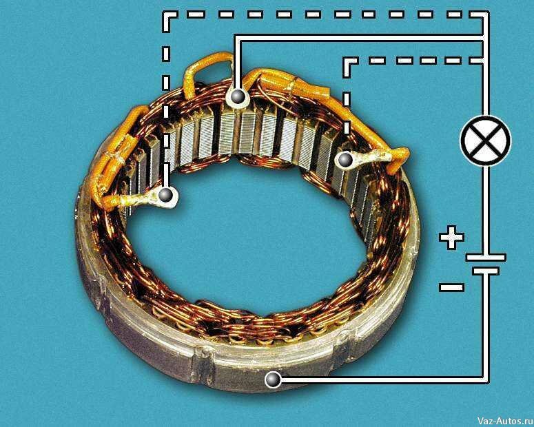
The electrical circuit \ Fig. 7 \ consists of a battery and a light bulb, this circuit is comparable to that of a pocket flashlight. One end of the negative potential wire is connected to the stator core, the other end of the positive potential wire connects to one of the brought out ends of the stator windings. If the wires are connected the other way around, that is, "plus" to the stator core, "minus" to the output end of the stator winding, nothing changes from this.
In the presence of insulation breakdown, when the stator winding is closed with the core, the light in this electrical circuit will be on. Accordingly, if the light does not light, then the stator winding is not closed with the stator core.
This method of diagnosis \ Fig. 7 \ is not complete. Accurate diagnostics is carried out only with an Ohmmeter device or a Multimeter device with a set resistance measurement range, for subsequent measurement of the resistance of the stator windings.