Double-circuit gas boiler, Ariston gives error 607 - DIY repair Part 3
Dear visitors!!! If suddenly you decide to repair a gas boiler with your own hands, without having the proper qualifications for that, then you must understand that you are going to interfere with the design of gas equipment. The information in this blog is provided for informational purposes only, how what I encountered and how I fixed it in my case.
You must understand that you perform all work at your own peril and risk, and therefore, before taking on, think about whether it would be better to turn to specialists.
The first malfunction that happened to my boiler and laid the foundation for studying this unit was as follows, the boiler does not light up on the display error - 607. And it's winter outside, brrrr cold. Let me remind you that we are talking about the Ariston Clas 24 FF boiler.
So, having a specialty in radio engineering and a little time to stay warm, I perform an autopsy and start looking. What I managed to find out and how to solve this as a typical problem later turns out to be.
The boiler does not light up on the display error - 607
If the boiler behaves in this way, we also pay attention to one more detail, the combustion products exhaust fan is constantly running in the boiler. Even if you turn off the boiler with the button on the control panel, it will still be spinning.
It will stop only when it is completely de-energized by unplugging the boiler from the outlet. And as soon as you plug it back in, the fan starts spinning right there. This symptom is one hundred percent guarantee of the malfunction described below.
Cause fan control relay stuck - treatment, relay replacement. In general, many boiler malfunctions are associated with the relay, and since all this refers to malfunctions of the electronic control unit of the ECU, the service technicians sometimes recommend replacing the entire ECU, and this is very decent money.
Repair of the electronic control unit - do it yourself
In this topic, I do not just want to point out the reason - they say the relay is stuck - in this topic you will get acquainted with why the boiler reacts so to a relay failure, which relay on the board is responsible for the fan, how to replace it and where to get it.
Well, in the next notes I will talk about other malfunctions associated with the ECU and not only. First, we look at the block board and the location of the relay.
RL01 - Fan control relay. RL02 - Three-way valve control. RL03- Pump speed control. RL04 - Pump control. RL05 \ RL06 - Provides power to the ignition unit and the gas valve.
The serial numbers of the relays are indicated as they are indicated on the board. The malfunction we are talking about now is caused by a relay malfunction. RL 01 relay type JZC-43F (3A 30VDC)
It is this relay that is responsible for controlling the fan.
The problem is that at that moment it was not possible to get such relays, and as I already mentioned it was winter, there was not enough time for repairs. Therefore, for the critics of this method, I will say right away that I did what was possible under those circumstances. I installed a larger relay and powered by a 24 volt coil.
As you must have noticed, the native relays are powered by 30 volts. Therefore, to make life easier for the 24 volt relay, I used the L7824CV stabilizer. This is a simple regulator with an input voltage of up to 35 volts, the output of which is 24 volts. Pin 1- This is an input, 2- This is a common, negative wire, 3- Voltage output 24 V.
1 and 2, the terminals of the stabilizer, observing the polarity, were soldered to the board, right where the relay coil leads should be soldered, and the contacts of the coil of the new relay, neatly wiring, soldered to the stabilizer, pin 2 (you can go straight to the heat sink where the bolt hole is also a mass ) and 3. So the relay coil was powered at 24 volts. Also, carefully, with wiring, we connect the group of contacts on the relay (you need a freely open one) with the board, those two points that will have to be closed by the contacts of the new relay.
Everything was done carefully, followed by insulating the joints with a heat-shrinkable tube. But as subsequent experience showed, all these troubles with an additional stabilizer turned out to be superfluous.
Subsequently, when another relay failed, I installed the relay at 24 volts and did not bother with the stabilizer, it also works, for a long time, but the truth is, compared to the first option, it heats up noticeably more.
Relay for boiler Ariston
Then, much later, analogs of the required relays were found on Aliexpress. These are OMRON G5NB-1A-E or Panasonic ALD124 24 V relays. They are also at 24 Volts, but this, as it turned out, is not a problem. The relays are made and look great, probably the original. So now I have some margin.
Addition: If you order these relays on Aliexpress, then pay attention to the fact that exactly the same relays are supplied with power for the winding under voltage and 5 and 12 volts. You need to find those that are 24 volts.
I already had to repair the boiler to my friends and use one of the "Omron" relays that I received: It got up like a native, it works perfectly. By the way, sellers generally offer these relays in batches of 10 or 50 pieces. That's how I ordered the batch. Later I found a seller from whom you can order them individually at a good price, the reviews are good. Link to this seller, by the way, it is possible to use Cashback.
P.S I would like to add about cashback, for a few small purchases I received $ 2.32. So it really works. Register and get a refund on every purchase. About

For those who are interested in why the gas boiler does not light up when the fan is running, read on.
Why does the gas boiler go out, or rather, the boiler does not light up?
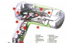
The wall-mounted gas boiler has several degrees of protection, for your own safety and to protect the boiler from more serious damage. One of the elements of the safety group is a pressure switch or, as it is called in the manual for the boiler, "air pressure switch" (Boiler operation and repair manual)
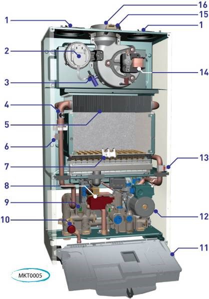
In the given drawing, the air pressure switch (Pressostat) is located under No. 2,
No. 14 Fan motor for exhaust gases (combustion products)
No. 3 Air pressure take-off with condensate drain.
By the way, in my boiler, this node number 3 was made differently. I had a so-called venturi tube which also has a certain protection function, but more on that in the next post.
Let's get back to our fault: So, as it should be. In short, after the start command is received from the control unit, the fan control relay is turned on.
In the chamber with a turbine (Snail), a thrust is created which, through a venturi tube, transfers a vacuum to the pressure switch in which the membrane is retracted with the contacts closed, which in turn informs the control unit that everything is in order - there is a thrust, you can work, we give a spark!
Thus, in a working boiler, the order is as follows:
START-UP COMMAND -> FAN -> PRESSOSTAT -> GAS VALVE and ISKRA.
But what happens when the fan control relay sticks? The fan receives power as soon as the boiler is plugged into the socket. It starts to rotate, creates a vacuum and the contacts of the pressure switch are closed even before the start command is received. The control unit does not leave this unnoticed and cancels the ignition command, displays an error 607 - which means: The air pressure switch worked before the ignition began.
So with a stuck relay, the following is obtained:
FAN -> PRESS STAT -> START COMMAND -> ERROR 607
These are the pies! That's all.