Error H 45, problems with DHW, safety valve and NTCs sensor
A few more tricks in repairing a double-circuit boiler Ariston, namely tricks, in order to describe everything in detail, specially opened his boiler and took a photo. I once wrote about this on one of the forums, but decided to describe everything in more detail, in pictures, here on this site.
It's about
The boiler does not supply hot water
The problem manifested itself as follows - when opening the hot water tap, the double-circuit boiler sometimes worked normally, but more often it simply did not light up, and did not give any errors. He simply did not react in any way, as if no tap was opening. At the same time, everything worked well in heating mode. It was also noticed that if the water pressure is made stronger, then the boiler worked more often.
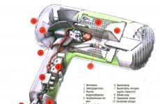
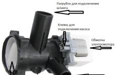
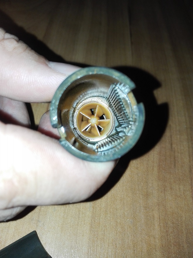
The electronic brains of the boiler "understand" that hot water is open and it is time to switch to DHW mode thanks to the "Flow meter." Cold water passes through it, rotates the turbine inside which there is a magnet, the magnetic field acts on the reed switch located in the outer part of the sensor and this signal is determined by the electronics as a command to turn on the boiler in sanitary mode (DHW)
Since everything happens like this, then suspicions immediately fell on the fact that the water flow sensor, also known as the flow meter, was clogged with dirt and the turbine does not rotate, unfortunately the cleaning did not give anything. But logic said that you need to drip there and it did not disappoint.
During the subsequent more detailed disassembly, it was noticed that the plane of the impeller was so polished that it literally stuck to the body, if you were holding ceramic elements from a half-turn tap in your hands, then you know what I'm talking about. And this sticking, oddly enough, interfered with the rotation.
Let's start repairing: I carried out this procedure several years ago, everything works fine. Today I specially removed and disassembled the flow meter in order to shoot everything and provide it to you.
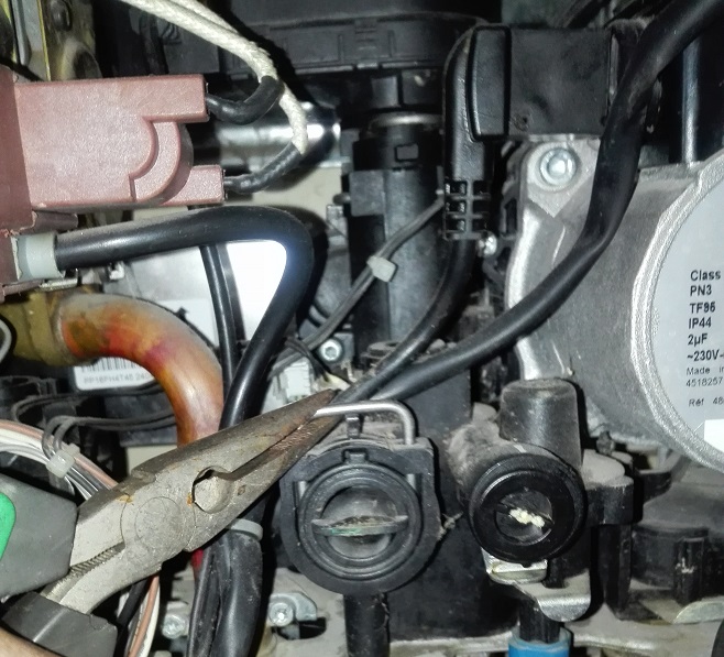
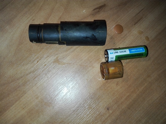
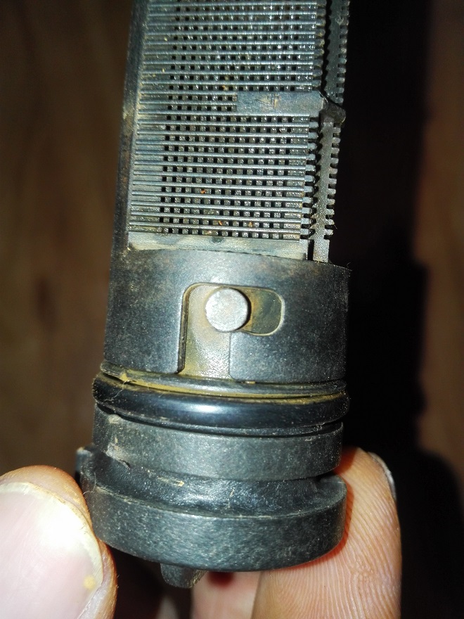
Before starting work, do not forget to disconnect the boiler from the mains. Turn off the tap for cold water supply to the boiler, then be sure to release the pressure to drain water from the boiler, for example, through a safety valve, place some container under its nozzle. Only after that we remove the bracket that fixes the water flow sensor.
And here it is! Now we need to remove it from the case. See below.
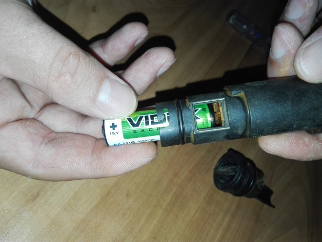
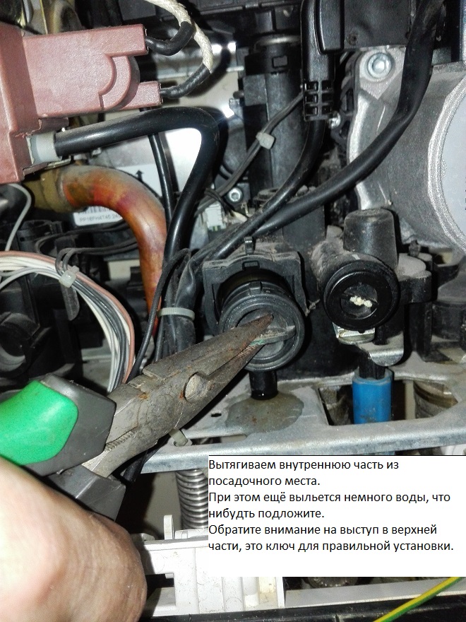
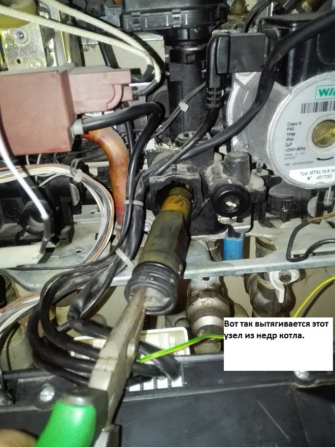
It is convenient to do this with a finger-type battery, it just goes inside, and with it we squeeze out the node we need.
The extraction is complete, the impeller is covered with a red bloom from water, it also does not hurt to wipe it off.
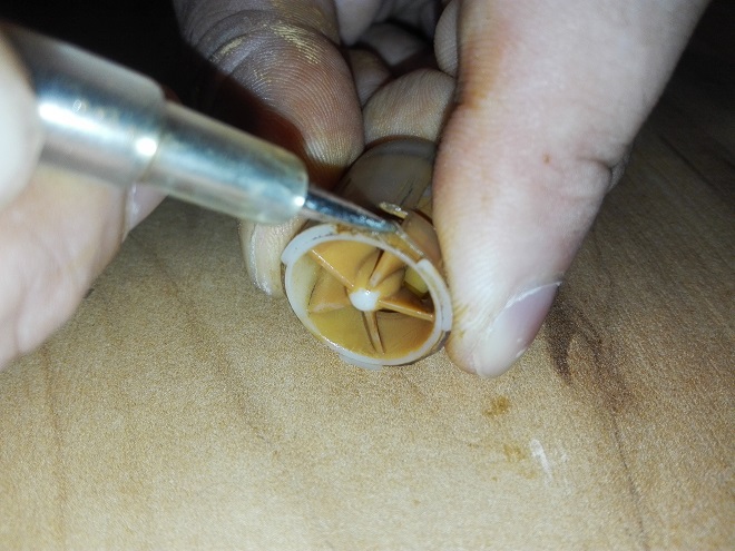
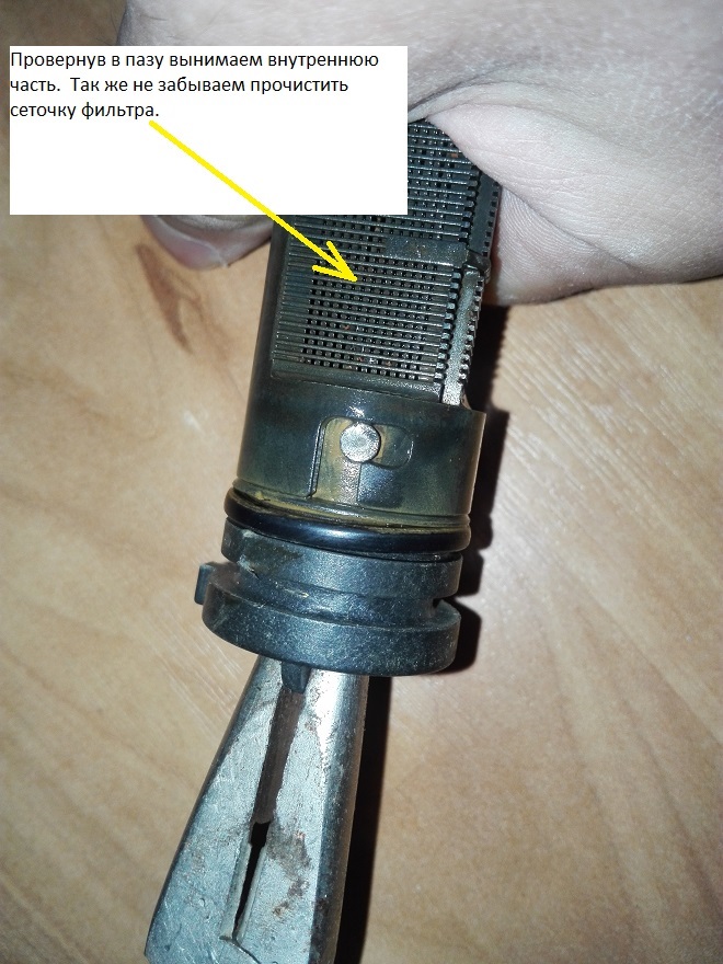
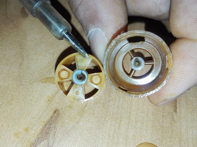
Now you need to carefully open this assembly, there are three latches, one of them will be wider than the others, this is the key for correct assembly.
In the top photo, I use a screwdriver to point to a thin PTFE washer. It was her that I put there in order to increase the gap between the plane of the impeller and the housing.
Without the washer, being on the axis, the planes of the impeller and the body touched and polished, like the magnets adhered to each other and the impeller did not rotate, this was the reason that the brains of the boiler did not receive a signal of passing water.
I removed the washer from the mechanism from an old cassette tape recorder (I have a lot of this junk), but in general it can be cut out of dense polyethylene yourself.
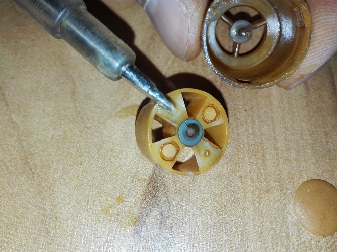
This photo shows that these planes did not have contact, they are red from the water.
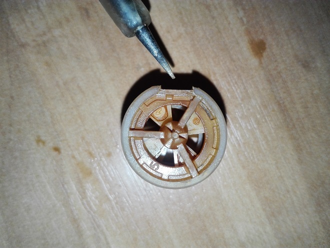
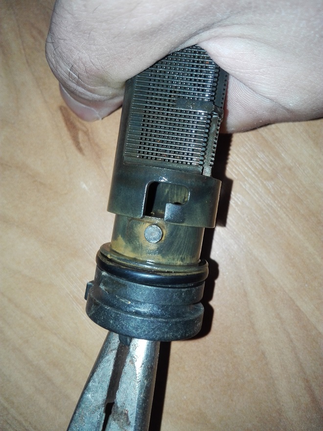
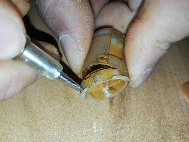
Putting it back together, pay attention to the notch indicated above. It should be directed in a certain direction when installing the unit into the case. 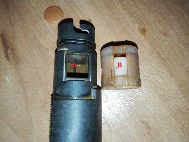
Namely, you need to combine sides A and B. Otherwise it will not fit. A battery will come to the rescue again to plant the knot all the way.
We insert into the grooves and turn, pay attention that the projections and guides on opposite sides have different sizes. Solve a logic puzzle ????
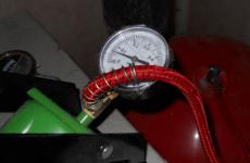
That's it, now we insert all this into the boiler, fix it with a bracket and do not forget to open the tap and supply the boiler with water to the required pressure.
After powering up the boiler, I recommend turning on the purge mode in order to expel air from the heat exchangers. To do this, press the ESC button for five seconds, the purge mode will start the circulation pump, this mode will start for 6 minutes. It can be disabled manually by pressing ESC again.
With this point, perhaps everything. Let's move on to the next tricky way.
No DHW, the boiler generates an error H 45 Check the NTC sensor
This problem also arose with hot water supply from a double-circuit boiler Ariston Clas 24FF
The problem manifested itself in the following way, turning on the hot water supply, the boiler ignites, but after a few seconds it goes out and gives an error H45.
The problem of this malfunction in the NTCs sensor The temperature sensor on the supply to the DHW circuit. By the way, not all modifications of Clas 24 boilers have this sensor. But it’s in my cauldron.
NTC sensors These are thermistors. These are elements that change their resistance depending on the temperature in the manual there is a table in which the dependence of resistance on temperature is indicated.
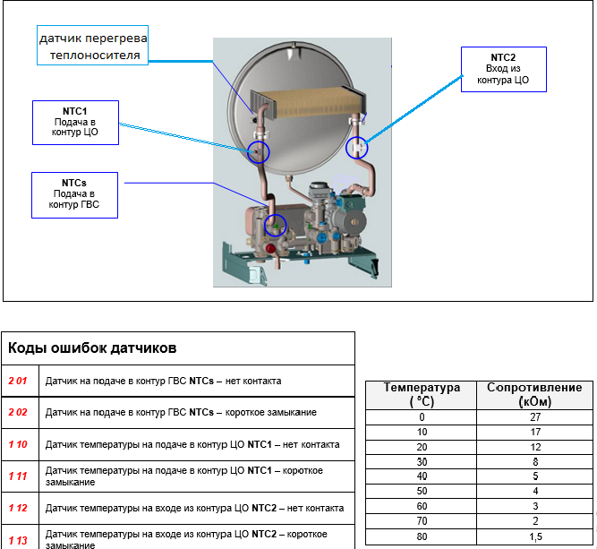
When I measured the resistance of the sensor with a multimeter, it was 2.5 kOhm. According to the table, it should have such a resistance at a temperature of more than 60 degrees, but it was cold. Now it is clear why the boiler did not start in DHW mode, the sensor showed that the water was already too hot, why should it be heated?
After a while, I again measured the resistance of the sensor and it showed 10 kΩ, which is normal for the temperature of cold water. The sensor was not stable.
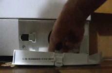
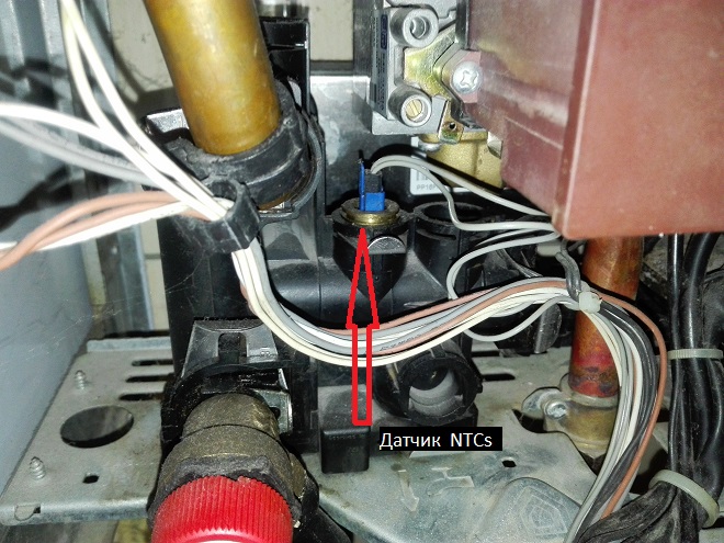
To check my version, I did the following: Disconnect the chip from the sensor. We look at the photo.
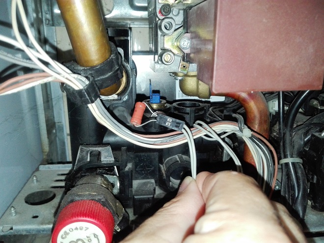
And in the holes of the chip, instead of the sensor, I inserted a resistor with a nominal value of 20 kOhm, with such a resistance, the “brains” of the boiler will perceive the water temperature as cold, less than 10 degrees. This is exactly how it turned out.
I start the boiler and ... Voila, everything works. Conclusion, you need to change the immersion sensor NTCs.
This is not a bad way to test if the sensor is working properly. But I think it's not worth deceiving the boiler circuit for a long time, you still need to purchase a sensor and replace it. (Remember to shut off the water and depressurize the boiler if you remove the immersion NTCs).
You need to understand that the resistance of the substituted resistor will not change when the water temperature changes, and this sensor, paired with another, regulates the strength of the flame, more precisely from the difference in readings between these sensors, the electronics regulates the strength of the flame. This is how the scale protection is implemented.
The safety valve allows water to pass through
There were also adventures with the safety valve. Once, after overhaul of the entire valve body of the boiler, the drain valve began to leak, that is, the gaskets, rubber rings were already worn out and began to leak.
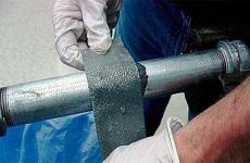
Way out: You can simply reel in a fumlent. But one day I had to apply creativity. There was no fumlenta, I was looking for a way out by rummaging in a box with various rubbish, and I found it…. in a syringe.
Yes, yes, in a medical, disposable syringe, it was lying among the trash because it was used as an oiler for machine oil. Its piston is a rubber cap, cutting off an extra cone from it, and one wide gasket was obtained, just instead of two rings. It worked great, and it still stands. The only thing that I still did was before installation, I applied a layer of grease like grease to this gasket. I used hammer drill lubricant.
And in another case, the safety valve leaked not at the junction with the main unit, but directly through the nozzle, that is, it did not hold the valve itself, and not its connection.
After disassembling it, it became clear why. Inside the valve, a rubber cap is pressed against the body by a spring, which closes the water outlet up to a certain pressure value. On the outer (locking) plane of this cap, a recess was pressed through and it interfered with tight contact with the body. Having removed this cap (it resembles a thimble in shape), you need to put something flat with a suitable diameter inside it, I cut out circles from cardboard and used them. This will slightly increase the pressing force and eliminate the leakage.
Well, now that's it! Share your opinion and your repair tricks.
There is a comment feed for this.