Centrifugal separators are. Centrifugal separator
Centrifugal separators are industrial equipment that is used to separate the flow. It belongs to the class of devices in which a swirling flow is used to separate multicomponent systems.
These devices are used to separate the gas stream and purify gases from a variety of mechanical impurities and moisture. Such gas purification refers to methods that are based on inertial precipitation of moisture.
The principle of the centrifugal separator
It is based on the direction of flow into the centrifugal dust collector. In such a device, the direction of air movement changes, and the substance is purified in a spiral. Due to the specially assembled separator design, heavier air continues to move in a spiral and separates from the purified air.
Precisely because the gas moves along a centrifugal spiral, a force is created that is many times greater than the force of gravity. Due to this, the gases are separated and purified from mechanical impurities. At the heart of the design of the separator is a special chamber, inside of which a centrifugal motion occurs. Such equipment is used for cleaning gases and gas condensate wells.
The entire gas-liquid flow enters the centrifugal separator through the inlet gas pipe and begins to rotate around the axis of the device. During rotation, the entire gas stream is cleaned of mechanical impurities and liquid. Centrifugal forces of the separator act on the flow, and it begins to gradually clear. During rotation, all contaminants are pressed against the walls of the device (80% of the contaminants are separated from the flow).
After that, the entire gas-liquid stream enters the separation bag and continues to rotate around the axis, slowly heading towards the outlet gas pipe. Further in the separation package, the last stage of gas purification takes place: they are separated from all impurities and excess moisture. After complete cleaning, the impurities pass through the internal flow under the influence of the force of gravity and exit downward through the drainage branch.
The device of the centrifugal separator
All internal elements of the separator are made of high-strength material and are optimally constructed in order to increase the longevity of the device. On the surface there are special buttons with which you can adjust the separation process and adjust the required speed of operation. The construction of such a separator is based on seven facts of separation (they are simultaneously considered constructive steps that are used to separate the gas-liquid flow).
The centrifugal separator consists of the following elements:
- Flanges
- Outlet gas connection
- Guiding Confuser
- Housing
- Deflector
- Separation package
- The false bottom
- Fluid discharge connection
- Inlet gas inlet
Positive sides of the centrifugal separator:
- High separation efficiency
- Maximum cleaning of all impurities and mechanical impurities from equipment
- Stable and long can work in different modes
- No power required, since the device operates without automation
- Minimum head loss on the separator
- Increased Throughput
- Optimal and affordable cost
- Long warranty service life
Centrifugal separation The processes of separation of inhomogeneous phases in centrifuges and hydrocyclones based on the action of centrifugal forces are called.
For centrifugation, centrifuges are used in which, depending on the design, centrifugal deposition or centrifugal filtration is carried out. For the deposition, centrifuges having a rotor with a continuous wall are used, and centrifuges with a perforated rotor wall for filtration. Suspensions can be separated in devices of both designs, and emulsions - only in devices with a solid wall of the rotor. For the implementation of these processes, precipitation and filter centrifuges are produced.
When separating suspensions in filter centrifuges, the liquid is filtered through the perforated wall of the rotor, and solid particles are retained by it. The precipitate formed on the wall is discharged in a continuous or batch mode.
In sedimentation centrifuges having a rotor with a solid wall, a solid phase with a higher density is deposited on the wall, and the liquid phase forming the annular layer closer to the axis of rotation is withdrawn from the apparatus. Similarly, there is a separation of emulsions: a solid layer of the rotor forms a layer of a denser liquid.
The classification of industrial centrifuges is carried out according to the following features: the principle of separation (the main design feature), the method of discharge of sediment, tightness, explosion protection, the possibility of controlling the temperature of the separated mixture.
When selecting a centrifuge, it is necessary to take into account, in addition to the operating conditions, the properties of the separated mixture, the dispersion of solid particles, the viscosity of the dispersion medium, the difference in the densities of the separated phases (the latter factor does not belong to the centrifugal filtration process, since in this case the difference in the densities of the two phases does not affect the efficiency of the process separation), the concentration of the substance in the liquid phase.
The efficiency of separation of materials in a centrifuge is determined by the factor of separation K, which shows how many times the velocity of a particle moving under the action of a centrifugal force is greater than its sedimentation rate under the action of gravity:
where w is the angular velocity of the rotor, rad / s; g is the acceleration due to gravity, m / s 2; n - rotor speed, min -1
Thus, with increasing radius and speed of rotation of the rotor, the separation factor and, consequently, the efficiency of the centrifuge operation increase.
When calculating the productivity of a centrifuge, it must be remembered that the separation of the solid phase from the liquid in the centrifuge occurs only when the residence time of the suspension in the rotor n is sufficient for the solid particle to reach its wall. The residence time of the liquid in the device:
where V is the volume of the apparatus; Q is the volumetric velocity of the liquid passing through the apparatus.
The most important role in centrifugation is played by the system of discharge of sediment, which can be manual, screw, knife, gravity, piston, inertial and vibrational.
The material from which the parts of the centrifuges are made must be resistant to the media that will affect it. For the manufacture of centrifuges used alloyed corrosion-resistant steel, titanium alloys, cast iron, plastics, rubber.
The largest group of machines are sedimentation horizontal centrifuges with auger discharge of sediment OGS, operating in a continuous mode. The auger is located inside the rotor and rotates together with it in one direction, but at different speeds, which allows discharging from the rotor the precipitate of the solid phase formed on its wall. GGS centrifuges are used to separate suspensions with a solids concentration of 1 to 40% (by volume) with a particle size of more than 5 μm with a phase difference of more than 0.2 g / cm. In addition, these centrifuges are used for hydraulic classification of suspensions for particle size and for other purposes. In accordance with the purpose, centrifuges of the GGS type are subdivided into clarifying, classifying, dehydrating and universal.
The productivity of centrifuges of the GGS type for suspension is 2-80 m / h; they have a rotor with a diameter from 200 to 1000 mm, rotor rotation speed from 6000 to 1000 min -1 and, accordingly, the separation factor is from 4000 to 560.
In Fig. 32 shows the device of a continuously operating horizontal sedimentation centrifuge of the OGSH-501K-10 model.
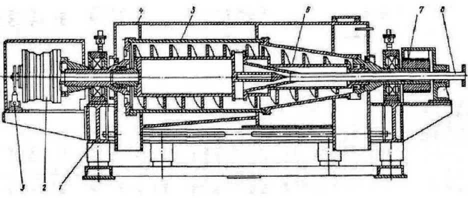
Fig. 32. Device of centrifuge OGSh-501K-10
1 - bed; 2 - planetary reducer; 3 - gear reduction mechanism; 4 - the casing; 5 - rotor; 7 - driving belts; 8 - power pipe
The machine is designed for dehydration and thickening of sewage sludge using flocculants. It has an extended counter-current rotor and a device for regulating the relative speed of rotation of the screw in order to select the optimal operating mode.
The main characteristics of the OGSh-501K-10 centrifuge are as follows:
Industrial automatic horizontal filtration and precipitation centrifuges such as FGN and OGN with knife removal of sediment are widely used by industry. They have a simple design, high separation quality, the ability to process suspensions over a wide range of concentrations and particle sizes of the solid phase. In Table. 13 shows some characteristics of automatic horizontal centrifuges.
Table 13. The main characteristics of automatic horizontal centrifuges
Centrifuges such as FGN and OGN are hermetic and can work in explosive areas and in rooms with high humidity. However, the frequency of operation of this class of centrifuges, their high metal content and a number of other shortcomings, limit the scope of their application.
In Fig. 33 shows the design of an automatic horizontal centrifuge with knife discharge of the FGN-633K-02 sediment with a rotor diameter of 630 mm. The machine can be installed in explosive rooms of class B-1a. The centrifuge parts in contact with the slurry being processed are made of stainless steel. To remove insoluble residue from the surface of the rotor, the centrifuge is equipped with a special mechanism, which has its own drive.
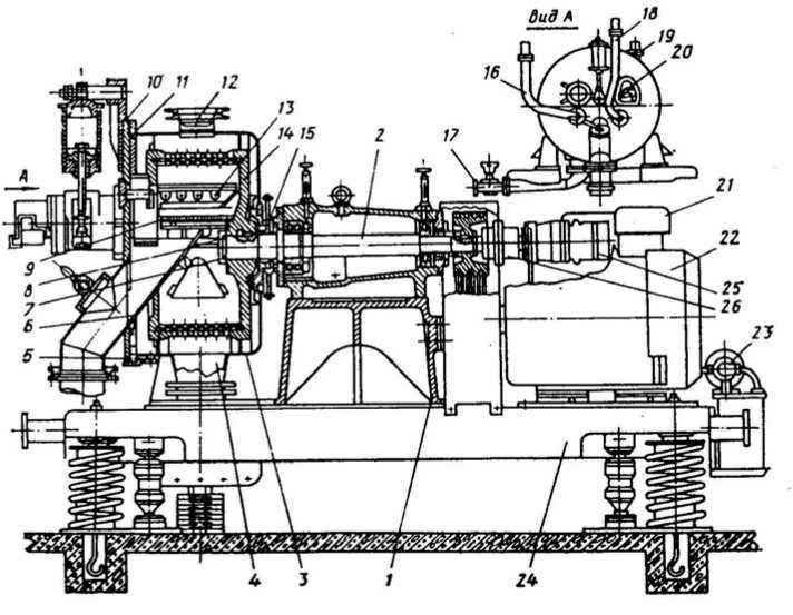
Fig. 33. The device of the centrifuge FGN-633K-02
1 - bed; 2 - the main shaft; 3 - a casing; 4, 5 - branch pipes for tapping the filtrate and liquid poured over the side of the rotor; 6-discharge hopper; 7 - a nut; 8 - protective cap; 9 - brushes; 70 - cover of the casing; 11-gasket; 12-pipe for suction of vapors and gases; 13 - rotary knife; 14-rotor; 15-sealing seal; 16, 18-loading and washing tubes; 17-split valve; 19 - blowing pipe of inert gas; 20 -load controller; 21, 23 - oil pump stations; 22-electric motor; 24 - vibration isolation device; 25 - the hydraulic motor; 26 - overrunning clutch
The filtering horizontal centrifuges with pulsating discharge of the FGP sediment are more perfect. In centrifuges of this type having a horizontally located rotor, the discharge of the sediment is carried out by a pulsating pusher. Technical characteristics of FGP centrifuges are given in Table. 14.
Table 14. Technical characteristics of centrifuges with pulsating unloading of solid phase
In Fig. 34 shows the device of a high-performance, continuously operating horizontal centrifuge with pulsating unloading of the 1 / 2FGP-145 sediment. The machine provides good separation of the suspension in large volumes, providing a solid phase moisture of not more than 5%.
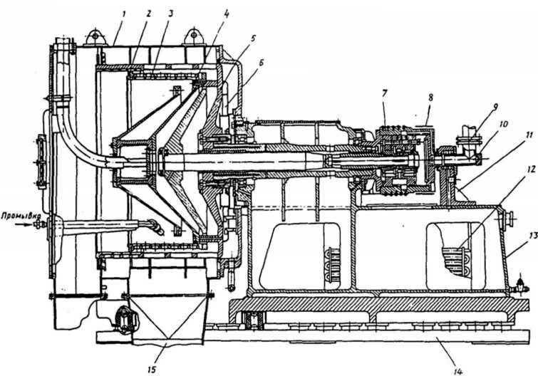
Fig. 34 Centrifuge device 1 / 2FGP-145
1 - the casing; 2 - support ring of the 1st cascade of the rotor; 3 - filter screen of the 1st cascade of the rotor; 4 - textolitic O-ring; 5 - the bottom of the 2 nd cascade; 6 - troughs supplying washing liquid to the rear part of the rotor; 7 - the hydrocylinder; 8 - the tape brake; 9 - metal plug; 10 - corner; 11- end clutch; 12 - refrigerator; 13 - bed; 14 - plate of vibration isolation; 15 - tapping point of filtrate
These centrifuges are designed to separate well-filtered concentrated slurries with a solids content of more than 20% (by volume) with a particle size of more than 100 μm. Advantages of centrifuges such as FGP - filter continuity, the possibility of washing the sediment, high degree of separation and productivity. They are easy to operate and have low energy and metal consumption.
To separate highly concentrated suspensions containing solid particles larger than 150 μm, a continuous horizontal centrifuge with a screw discharge of the FGSh-401K-01 sediment is used at a volume concentration of solid phase of 40-50%. The centrifuge capacity is 5000 kg / h with a maximum diameter of a conical rotor of 400 mm and a maximum separation factor of 1500.
A large group of machines are centrifuges suspended with upper and lower drive type FMB and FDM. They are used when a high degree of dewatering of the solid phase is necessary, in small scale production, to separate difficult-to-filter suspensions containing particles larger than 10 μm. Suspended sedimentation machines with a lower drive type OMD and OMB are used for settling liquids in cases where the use of settling centrifuges of continuous action is impossible or inefficient. In Table. 15 shows the characteristics of some suspension centrifuges with a lower drive.
Table 15. Some characteristics of suspension centrifuges with a lower drive
In Fig. 35 shows the device of a suspension centrifuge with a lower drive and a lower discharge of the sediment of the model FMD-125. The centrifuge is hermetically sealed and can be used in explosive rooms of class B-1a.

Fig. 35 Device of the centrifuge ФМД-125
1 - the rotor; 2 - a casing; 3 - charging cone; 4 - rotor support; 5 - suspension; 6 - the rim; 7 - housing; 8-tension mechanism; 9-drive
A special group consists of tubular centrifuges having a high rotational speed of the tubular rotor. They are used for clarifying suspensions (centrifuges of the OTP type) and for their separation (PTR type). Clarifying centrifuges can work in a continuous mode. Separating centrifuges operate in a batch mode, which is associated with manual discharge of sediment. These centrifuges are used to clarify low-concentration suspensions and to separate persistent emulsions (for example, to purify water from used oils). Tubular centrifuges have a rotor speed of up to 15,000 min -1, maximum rotor loading of up to 150 mm in diameter is 20 kg.
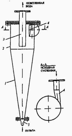
Fig. 36. General view of the hydrocyclone
A wide application for separation of particles from 0.2 to 0.5 mm in size (sometimes up to 1 mm) from liquids is found in hydrocyclones. Hydrocyclones, like centrifuges, operate on the principle of centrifugal separation.
The hydrocyclone is shown in Fig. 36. It consists of a cylindrical and conical parts. The liquid in the hydrocyclone rotates as a result of the movement of the suspension through the tangential branch pipe 4 located at the top of the cylindrical part 2. The conical part of the hydrocyclone 1 ends with a slurry nozzle 5 through which a precipitate separated from the slurry to be treated is discharged. The clarified liquid flows through a drain pipe 3 located along the hydrocyclone axis.
The displacement of particles of suspended matter in the field of action of the centrifugal force, which develops during the operation of the hydrocyclone, is many times more intense than precipitation by gravity.
The factor of separation K for hydrocyclones varies in the range from 500 to 2000. In hydrocyclones, as in centrifuges, the separation of suspensions occurs under the action of centrifugal force, but in the mode of action they differ significantly.
In a centrifuge, the slurry rotates along with the drum and, at a constant angular velocity, does not practically move along its surface. At the same time, no tangential forces act on the particles. In the hydrocyclone, large tangential forces act on the particles of the suspension, supporting them in continuous relative motion. Between the layers there is a shear stress acting on the solid particle as a transverse force.
To improve the separation of suspended particles from liquid in centrifuges at a constant frequency of rotation of the drum, it is necessary to increase its diameter. In hydrocyclones, on the contrary, this is directly proportional to the decrease in the diameter of the apparatus. Reducing the diameter of the hydrocyclone leads to a decrease in its productivity. In those cases where more fine cleaning product with a significant amount of it, use battery hydrocyclones (multi-hydrocyclones), which are several parallel-connected elementary hydrocyclones.
In the hydrocyclone, the rotational motion of the separated suspension is determined, first of all, by the law of conservation of the angular momentum.
To calculate the separation in hydrocyclones, it is important to know the nature of the distribution of the radial and axial velocities of the fluid and the corresponding components of the particle velocity. Normally, in the zone between the cylindrical part of the body and the branch pipe for the outlet of the clarified liquid, the value of the axial velocity is assumed equal to the average expenditure rate. The theory and calculation of hydrocyclones of various types are sufficiently fully expounded in the special literature.
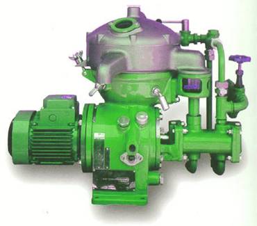
Centrifugal separators
Centrifugal separators - industrial equipment intended for separation of flow, using a centrifugal separation method. Centrifugal separators belong to the class of devices (equipment) - separators Using a swirling flow to separate multicomponent systems. A feature of such devices is high quality separation (separation).
The centrifugal separator includes:
- centrifugal gas-liquid separators intended for separating the gas-liquid flow and cleaning the gas (air) flow from dripping moisture and mechanical impurities. A feature of such devices is the absence of moving and rotating parts and elements, as well as small overall dimensions and weight parameters
Centrifugal cleaning of gas (air) refers to methods of gas purification based on inertial precipitation of moisture and (or) suspended particles by creating a gas stream and a centrifugal force suspension in the field of motion. Centrifugal method of gas purification refers to inertial methods of gas (air) purification.
Operating principle
The gas (air) flow is directed to a centrifugal dust collector in which, by changing the direction of movement of the gas (air) with moisture and suspended particles, usually in a spiral, gas is purified. The density of the slurry is several times greater than the density of the gas (air) and it continues to move in inertia in the same direction and is separated from the gas (air). Due to the movement of gas along the spiral, centrifugal force is created, which is many times greater than the force of gravity.
Efficiency
A relatively fine dust is precipitated, with a particle size of 10-20 μm.
see also
Wikimedia Foundation. 2010.
Watch what is "Centrifugal Separators" in other dictionaries:
This term also has other meanings, see Separator (values). Separator apparatus, which divides the product into fractions with different characteristics. Contents 1 Separation 2 Types of separators ... Wikipedia
Fossils (a gravity separation, Gravitationsaufbereitung, concentration gravimetrique, preparation gravimetrique, and concentracion gravimetrica) separation of minerals by density in a force field ... ... Geological encyclopedia
- gravity preparation, gravity concentration, German Gravitationsaufbereitung f, Schwerkraftaufbereitung f) process and technology of mineral enrichment based on the use of gravity, with ... ... Wikipedia
nominal - 3.7 nominal: A word used by the designer or manufacturer in phrases such as nominal power, nominal pressure, nominal temperature and rated speed. Note Avoid using this word ... Dictionary-reference terms of normative and technical documentation
67.260 - Installations that are used for harvovoy promyslovosty DSTU GOST 8.482: 2008 GSI. Glass gyrometers. Methods and means of verification (GOST 8.482 83, IDT) GOST 12.2.092 94 SSBT. Electromechanical and electro-heating equipment for enterprises ... ... Pozhazhchik national standards
GOST 13477 (68) Centrifugal ship separators. Rated performance. ОКС: 47.020.20 КГС: Д44 Ship mechanisms and boilers Effect: С 01.07.68 Changed: IUS 6/73, 5/80, 10/84 Note: reissue 1984 Text of the document: GOST 13477 ... ... Handbook of GOSTsHandbook of GOSTs
A; m. [from the lat. separator separator] 1. An apparatus for separating one substance from another or separating it from a mixture or composition. Milk with. Magnetic with. C. for separation of egg yolk. Running milk through with. (for separating the cream, going to ... ... encyclopedic Dictionary
Disc Centrifugal Separator
1 - a drum; 2 - conical plates; z - holes in the plates; 4 - channel for the exit of a light liquid; b - a pipe for supply of liquid; 7 - channel for the exit of heavy liquid.
Centrifugal separators have found wide application in petrochemical, oil refining, and other industries, where they are used to separate persistent oil emulsions. This type of separator is used both for separating oil from gas and for separating water from oil.
Manufacturers produce centrifugal separators in two versions - vertical and horizontal. In view of the fact that vertical centrifugal separators are characterized by higher efficiency and productivity, the cost of these devices is higher than that of horizontal ones.
The principle of operation of a centrifugal separator is based on the fact that an inhomogeneous emulsion, hitting the field of centrifugal forces, is divided into different phases with different specific gravity. The process of precipitation itself goes according to the Stokes law. According to this law, the frictional force inside the vessel depends on a number of parameters, namely the velocity of the particles, the dynamic viscosity of the liquid, and the radius of the container.
A properly designed separator must dissipate the energy of the material that comes in, perform the initial gravity separation when liquid enters the device, hold it for a sufficient period of time to completely separate it, and prevent re-mixing of the separated materials, for example oil and water.
The principle of the centrifugal separator
In general, centrifugal separators are equipped with a filter, which is installed on the side of the device. And initially the emulsion is supplied to the filter, which produces its initial purification from solid suspended particles. After cleaning, the material is channeled through special channels into the separation chamber of the apparatus.
The main working part of the centrifugal separator is a drum that consists of tight rings, a locking piston, various trays, a tray holder, a base and a lid. Once in the separation chamber, the emulsion is in the space between the plates, where the main process is carried out, during which the heterogeneous system is divided into phases.
Light liquid is pushed back to the drum axis, then it enters the outer channels of the tray holder. From there, the liquid enters the chamber for light ends, which is located in the cover of the device. In turn, the heavy liquid also enters the chamber provided for it in the lid of the device, after passing through the gravitational washer.
During the process in which the liquid is separated, a precipitate is collected in the drum, which needs to be removed periodically. For this purpose, water is supplied to the cavity located above the locking piston, so that the sediment, subjected to centrifugal force, enters the discharge channels, and already from them into the compartment intended for the slurry. After the cleaning process is completed, the separation resumes. All cycles of the centrifugal separator are automated.
Selecting a centrifugal separator
When choosing a centrifugal separator, one must be guided by what the characteristics of the working material are, including also its volumes, type of flow, resistance, pressure, temperature.
The use of vertical centrifugal separators is most suitable in cases where there is a need for accumulation of large volumes of material. And in the emulsion itself contains a large number of suspended solids.
The use of horizontal centrifugal separators is advisable under conditions where the volumes of the material are small and the emulsion contains a large amount of dissolved gas.
If you take in general, then no matter what type of separator is, if its load is properly calculated, then the result will be the one that is needed.
If the article was useful, as a thanks use one of the buttons below - this will slightly increase the article's reining. After all, the Internet is so difficult to find something worthwhile. Thank you!


