Antennas of horizontal polarization. Basic materials for the manufacture of antennas Options for self-manufacturing television antennas in the photo
Despite the rapid development of satellite and cable television, the reception of terrestrial television is still relevant, for example, for seasonal residences. It is not at all necessary to buy a finished product for this purpose; a home decimeter (UHF) antenna can be assembled by hand. Before proceeding to the consideration of designs, we will briefly describe why this particular range of the television signal was chosen.
Why DMV?
There are two good reasons to opt for this type of structure:
- The thing is that most channels are broadcast in this range, since the design of repeaters is simplified, and this makes it possible to install a larger number of unattended low-power transmitters and thereby expand the coverage area.
- This range is selected for broadcasting "numbers".
Indoor antenna for TV "Rhombus"
This simple, but at the same time, reliable design was one of the most common in the heyday of on-air television.
Rice. 1. The simplest homemade Z-antenna, known under the names: "Rhombus", "Square" and "People's Zigzag"As can be seen from the sketch (B Fig. 1), the device is a simplified version of the classic zigzag (Z-design). To increase the sensitivity, it is recommended to equip it with capacitive inserts ("1" and "2"), as well as a reflector ("A" in Fig. 1). If the signal level is acceptable, this is not necessary.
As a material, you can use aluminum, copper, as well as brass tubes or strips with a width of 10-15 mm. If you plan to install the structure on the street, then it is better to abandon aluminum, since it is susceptible to corrosion. Capacitive inserts are made of foil, tin or metal mesh. After installation, they are soldered along the contour.
The cable is laid as shown in the figure, namely: it did not have sharp bends and did not leave the limits of the side insert.
Decimeter antenna with amplifier
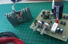
In places where a powerful relay tower is not located in relative proximity, you can raise the signal level to an acceptable value using an amplifier. Below is a schematic diagram of a device that can be used with almost any antenna.
 Rice. 2. Antenna amplifier circuit for the UHF range
 Item List:
- Resistors: R1 - 150 kOhm; R2 - 1 kOhm; R3 - 680 Ohm; R4 - 75 kOhm.
- Capacitors: C1 - 3.3 pF; C2 - 15 pF; C3 - 6800 pF; C4, C5, C6 - 100 pF.
- Transistors: VT1, VT2 - GT311D (can be replaced with: KT3101, KT3115 and KT3132).
Inductance: L1 - is a frameless coil with a diameter of 4 mm, wound with copper wire Ø 0.8 mm (2.5 turns must be made); L2 and L3 are 25 µH and 100 µH high frequency chokes, respectively.
If the circuit is assembled correctly, we will get an amplifier with the following characteristics:
- bandwidth from 470 to 790 MHz;
- gain and noise coefficients - 30 and 3 dB, respectively;
- the value of the output and input resistance of the device corresponds to the RG6 cable - 75 Ohm;
- the device consumes about 12-14 mA.
Let's pay attention to the way the power is supplied, it is carried out directly through the cable.
This amplifier can work with the simplest designs made from improvised means.
Indoor antenna made from beer cans
Despite the unusual design, it is quite functional, since it is a classic dipole, especially since the dimensions of a standard can are perfect for the arms of a UHF vibrator. If the device is installed in a room, then in this case it is not even necessary to coordinate with the cable, provided that it is not longer than two meters.

Designations:
- A - two cans with a volume of 500 mg (if you take tin, not aluminum, you can solder the cable, and not use self-tapping screws).
- B - places for fastening the shielding braid of the cable.
- C - central vein.
- D - the place of attachment of the central core
- E - cable coming from the TV.
The arms of this exotic dipole must be mounted on a holder made of any insulating material. As such, you can use improvised things, for example, a plastic clothes hanger, a mop bar, or a piece of wooden beam of the appropriate size. The distance between the shoulders is from 1 to 8 cm (selected empirically).
The main advantages of the design are fast production (10 - 20 minutes) and quite acceptable quality of the "picture", provided that the signal strength is sufficient.
Making a copper wire antenna
There is a design that is much simpler than the previous version, which requires only a piece of copper wire. This is a narrow band loop antenna. This solution has undeniable advantages, since in addition to its main purpose, the device plays the role of a selective filter that reduces interference, which allows you to confidently receive a signal.
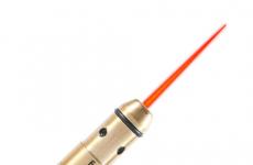
 Fig.4. A simple UHF loop antenna for receiving digital TV
 For this design, it is necessary to calculate the length of the loop, to do this, you need to find out the frequency of the “numbers” for your region. For example, in St. Petersburg it is broadcast on 586 and 666 MHz. The calculation formula will be: L R = 300/f, where L R is the length of the loop (the result is presented in meters), and f is the average frequency range, for Peter this value will be 626 (the sum of 586 and 666 divided by 2). Now we calculate L R, 300/626 = 0.48, which means that the length of the loop should be 48 centimeters.
If you take a thick RG-6 cable, where there is a braided foil, then it can be used instead of copper wire to make a loop.
Now we will tell you how the structure is assembled:
- A piece of copper wire (or RG6 cable) is measured and cut off with a length equal to L R .
- A loop of a suitable diameter is folded, after which a cable is soldered to its ends, which goes to the receiver. If RG6 is used instead of copper wire, then the insulation is first removed from its ends, by about 1-1.5 cm (the central core does not need to be cleaned, it does not participate in the process).
- The loop is installed on the stand.
- An F connector (plug) is screwed onto the cable to the receiver.
Note that despite the simplicity of the design, it is most effective for receiving "numbers", provided that the calculations are carried out correctly.
Do-it-yourself indoor antenna MV and UHF
If, in addition to UHF, there is a desire to receive MV, you can assemble a simple multiwave oven, its drawing with dimensions is presented below.

To amplify the signal in this design, a ready-made SWA 9 block is used, if there are problems with its acquisition, you can use a home-made device, the circuit of which was given above (see Fig. 2).
It is important to observe the angle between the petals, going beyond the specified range significantly affects the quality of the "picture".
Despite the fact that such a device is much simpler than a log-periodic design with a wave channel, nevertheless, it shows good results if the signal is of sufficient power.
Do-it-yourself figure-eight antenna for digital TV
Consider another common design option for receiving "numbers". It is based on the classic scheme for the UHF range, which, due to its shape, was called the "Eight" or "Zigzag".
 Rice. 6. Sketch and implementation of the digital eight
 Construction dimensions:
- the outer sides of the rhombus (A) - 140 mm;
- inner sides (B) - 130 mm;
- distance to the reflector (C) - from 110 to 130 mm;
- width (D) - 300 mm;
- step between the bars (E) - from 8 to 25 mm.
The cable connection point is at points 1 and 2. The requirements for the material are the same as for the Rhombus design, which was described at the beginning of the article.
Homemade antenna for DBT T2
Actually, all the examples listed above are capable of receiving DBT T2, but for a change, we will give a sketch of another design, popularly called the “Butterfly”.

As a material, you can use plates made of copper, brass, aluminum or duralumin. If the structure is planned to be installed on the street, then the last two options are not suitable.
Outcome: which option to stop?
Oddly enough, but the simplest option is the most effective, so the "loop" is best suited for receiving the "digit" (Fig. 4). But, if you want to receive other channels in the decimeter range, then it is better to stop at the "Zigzag" (Fig. 6).
The antenna for the TV should be directed towards the nearest active repeater, to select the desired position, rotate the structure until the signal strength is satisfactory.
If, despite the presence of an amplifier and a reflector, the quality of the “picture” leaves much to be desired, you can try to install the structure on the mast.

In this case, it is necessary to install lightning protection, but this is a topic for another article.
The length of the tubes, and hence the total length of the vibrator, depends on the frequency of the received television station. And it can lie in the range from about 50 to 230 MHz. This entire operating range is divided into 12 channels - they are marked on the TV's program selector knob. the second - 229-234 and then, respectively - 177-179, 162-163, 147-150, 85, 80, 77, 75, 71, 69, 66 cm. Therefore, before you start building the antenna, find out on which channel it leads broadcasts local TV center or repeater.
So, the length of the tubes was determined. Their diameter can be 8-24 mm (most often used, tubes with a diameter of 16 mm). Flatten one of the ends of each tube and attach the tubes with metal clamps to the Holder and? insulating material (textolite or getinaks with a thickness of at least 5 mm) so that the required distance is obtained between the remote ends, and the flattened ends are 60-70 mm apart from each other. Attach the mounting petals to the flattened ends with screws - they will serve as a kind of tube outlets. It is better, of course, to weld the petals to the ends of the tubes so that the contact is more reliable.

Install the tube holder. on the mast, which will later be installed on the roof. Now you need to connect a reduction to the antenna from a coaxial cable RK-1, RK-3, RK-4 or another with a wave impedance of 75 ohms. But it is impossible to solder the cable conductors directly to the tube leads. A matching device is installed between the drop cable and the antenna, which is a loop of two segments of the same coaxial cable. The length of the segments depends on the received television channel.
For the first channel, the size should be 286 cm, and 12 - 95 cm, for subsequent channels - 242 and 80, 187 and 62, 170 and 57, 166 and 52, 84 and 28, 80 and 27, 77 and 26, 74 and 25, 71 and 24, 68 and 23, 66 and 22 cm.
The connection of the matching device is shown in Figure 2. The central cores of the cable and the segments are soldered directly to the terminals of the tubes and to each other, and the metal braids are connected by segments of copper wire without insulation. Soldering must be strong and reliable, and soldering points are protected with insulating tape.
The matching loop and drop cable are attached to the mast. The length of the drop cable must be long enough to connect to the TV after installing the roof antenna. At the end of the cable, a connector is installed that plugs into the TV jack.
The antenna is strengthened with braces so that it stands firmly, and the vibrator is at a distance of at least 2 m from the roof.
To get the most powerful signal from the antenna, it must be oriented as accurately as possible to the television center (or to the repeater antenna). This work is best done by two or even three people. One slowly rotates the antenna around its axis, and the other, watching the TV screen, tells him about the change in contrast and image quality. The antenna is installed and fixed in such a position that the contrast is greatest and there is no multi-contourism in the image (the result of receiving a signal reflected from nearby buildings).
Separately, it is necessary to dwell on the materials that are used in the manufacture of the antenna. Antenna elements can be made of tubes, rods, strips or corners of any metal. In accordance with the surface effect, high-frequency currents flow exclusively along the surface of the metal, so a thin-walled tube or a solid rod of the same diameter is exactly the same in its properties.
Typically, television antennas are made of aluminum or its alloys. This is due to the fact that the antenna from such tubes is quite strong and light. However, the electrical properties of aluminum antennas are not high enough due to the fact that poor contacts are often formed at the junctions of antenna elements, caused by an oxide film covering the surface of aluminum alloys. This can lead to antenna failure over time.
It gets even worse when, when assembling the antenna, elements or coupling bolts from different metals are used. In this case, due to the contact potential difference, a galvanic couple arises, destroying the metal at the junction. Therefore, aluminum antennas are best connected using gas welding or, in extreme cases, using aluminum tie bolts, nuts and washers. Before assembling, it is useful to clean the elements at the joints well with a file and generously lubricate with technical petroleum jelly to prevent the formation of an oxide film.
In principle, the antenna can be made of any metal; copper, brass, bronze, steel or stainless steel. Compared to aluminum antennas, such antennas will of course be significantly heavier. In all cases, it is desirable to connect the antenna elements in such a way as to exclude the possibility of poor contacts due to corrosion or destruction from electrolysis. To do this, all connections are best welded or soldered. In this case, the antenna elements can also be made of different metals. If steel elements were used and soldered using an acid flux, the soldering points must be thoroughly washed with hot water to remove its residues, otherwise the flux residues will lead to severe metal corrosion for a short time.
It should be remembered that soldering serves only to ensure good electrical contact. Soldering with tin solders does not withstand mechanical loads. Therefore, it is necessary to ensure the strength of the connections by other methods (rivets, bolts, etc.), and after assembly, these connections should be soldered. The exception is brazing, which has sufficient strength. In order to avoid corrosion, the antenna, after complete assembly and soldering of the feeder with the matching device to it, is thoroughly cleaned of oxides and well painted over in several layers with oil or nitro paint. Synthetic car enamels can also be used. These dyes are good dielectrics and do not affect the operation of the antenna at all. It is undesirable to use aluminum paints, since they have a finite resistance value.
The cable connection points to the antenna elements must be sealed to prevent moisture ingress. The best sealing is achieved by using plasticized epoxy resin. Such a resin in the form of an epoxy adhesive of the EDP brand is available for sale in household goods stores. The place to be sealed is superimposed on a piece of plasticine, a recess of the appropriate shape is made in it and filled with resin. After it hardens, the plasticine is removed, and the surface of the resin is processed with a file to give it an even shape. For a good fit of the resin to the metal, it must first be degreased with acetone.
Based on the book by V.A. Nikitin "How to achieve good TV performance."
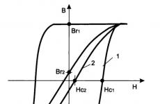
Symmetric vibrator. A symmetrical vibrator can be thought of as a long line, open at the end, with the wires rotated 180 degrees. The simplest, most commonly used antenna is a half-wave vibrator. A symmetrical half-wave vibrator is shown in fig. 11. 9. A symmetrical half-wave vibrator requires a symmetrical power supply. An unbalanced feeder line in the form of a coaxial cable can be connected to it, but only through a balancing device, which will be discussed in paragraph 11. 7.
The half-wave vibrator is powered at the current antinode (geometric center) and the input resistance is equal to the radiation resistance. Theoretically, the input impedance of a half-wave vibrator is 73 ohms, but this value is determined on the assumption that the antenna conductor is infinitely thin and the antenna is located infinitely high above the ground. On fig. 11. 10, a. the radiation pattern of a half-wave vibrator in the horizontal plane is given. She represents the eight. There are two radiation maxima perpendicular to the antenna, and two minima along the vibrator axis to 90 and 270 degrees. From these sides there will be neither reception nor radiation during transmission. The literature usually gives attenuation values in these directions, which
reach 38-40 dB, which is an attenuation of 80-100 times. The radiation angle in the vertical plane depends on the height of the antenna suspension above the ground. At an antenna height of L/4 (Fig. 11.10.6.), the radiation will be vertically upwards, and at a height of L/2 (Fig. 11.10, c.), the radiation will be at an angle of 30 degrees to the horizon. This antenna height is the best. By increasing the antenna height to 1 L we get two petals, as in the diagram in Fig. 11.10, g. The lower lobe, having 12-15 degrees, will provide communication with distant correspondents, and the one that has 45-50 degrees, with the near ones. True, the transmitter power will then be divided into two radiations.
Often, radio amateurs are faced with the question of how the metal and reinforced concrete roof affects, on which they mostly install

antennas, on the radiation pattern in the vertical plane. They influence, but they cannot be considered as an ideal earth.
To be able to put an equal sign between the roof and the ideal -ground, this surface must have at least an area equal to L ^ 2 .
In the HF and VHF bands, the wire diameter of a half-wave vibrator is rarely less than 2 mm, while the input impedance of the antenna is in the range from 60 to 65 ohms. From the graph (Fig. 11.11), you can determine the input impedance RBX of a half-wave vibrator, depending on the ratio L / d. Both quantities are taken in the same units, in meters or centimeters.
Determining the geometric dimensions of a half-wave vibrator, consider the difference between the "electric" and "geometric" lengths of the vibrator. In fact, the electrical and geometric lengths of the vibrator are equal only when the antenna conductor becomes infinitely thin. Using the graph, the shortening factor of the vibrator is determined depending on the L/d ratio.
The antenna can be made not only from a thin wire with a diameter of 2 - 4 mm, but also from copper or duralumin pipes of various diameters. With a smaller diameter of the antenna conductor, it is more narrowband, and with a larger diameter, its bandwidth increases. This must be taken into account when the overlap range is large. For example, for the range 28.0 - 29.7 MHz or in the VHF sections 144 - 146 MHz and 430 - 440 MHz.
Example. It is necessary to find the geometric length of a half-wave vibrator for a frequency of 145 MHz for a tube with a diameter of 20 mm, from which the antenna will be made. For a frequency of 145 MHz, L \u003d 206 cm. We get the ratio L / d206: 2.0 \u003d 103 According to the graph, we find K \u003d 0.91 (indicated by a dotted line on the graph). Then the required length of the half-wave vibrator is:
L / 2 x K \u003d 103 x 0.91 \u003d 93.7 cm. Antennas for the ranges of 160, 80, 40 and 30 meters, having a large length, can be made of bimetal, which is widely used in wire broadcasting. The steel core of such a wire is covered with a thick layer of copper and the wire has great strength. Such a wire is 3-4 mm in diameter. Table 11.1 shows the dimensions of half wave vibrators.
Table. 11.1 Dimensions of half-wave vibrators

For half-wave antennas fed in the middle (Fig. 11. 9), antinodes U and current minima I are formed at the ends of the vibrator. This indicates that there is a large resistance at the ends of the half-wave vibrator. When feeding a half-wave vibrator from the end, it is necessary to choose a different power scheme. The antenna is switched on through a matching device. As a matching device, a U-shaped circuit should be chosen, the input impedance of which can be equal to the wave impedance of the coaxial cable, i.e. 60 - 75 Ohm. On fig. 11.13 shows such an antenna connection scheme.
In modern urban planning, for the most part, high-rise buildings are being built. This can be used in the construction of the antenna farm of a radio amateur.
To install an antenna on the roof of a house, you must obtain permission from the relevant authorities.

Antenna for the range of 160 meters. On fig. 11.12 shows two antennas of the half-wave vibrator type, located at an angle of 90 degrees. By switching these antennas, all directions can be covered. Antennas A and B are the same length.
Their length according to table 11.1 is 75.79 meters. To match the high-resistance input of a half-wave vibrator, fed from the end, with a feeder made of a coaxial cable with a wave resistance of 60 - 75 Ohms, it is necessary to build a matching device in the form of a U-shaped circuit tuned to the middle frequency of this range. The U-shaped circuit is placed in a metal waterproof box, on which are installed: a high-frequency coaxial connector for connecting the feeder coaxial cable, two or three high-frequency bushings designed for high RF voltage, and a terminal for connecting a "counterweight" made in the form of a rectangle around the perimeter roofs - G. Its length is not critical. Feeder D can be placed in the ventilation duct going to your apartment. On Fig. 11.13 shows a diagram of a matching device. The metal box contains: HF choke, relay P1, P2, capacitors C1, C2, coil L and diodes D1, D2. The DC relay is low voltage, any type, but its switching contacts must be high frequency, designed for high voltage switching. Such relays were used in radio stations RSB-5 or another type. The relay is powered by a coaxial cable. When a positive voltage is applied, relay P1 is turned on, and a negative one - P2. Relay P2 can be used to connect another antenna, and its input impedance must be low-impedance. For example, a mid-fed half-wave vibrator or a quarter-wave vertical antenna. Capacitor C1 for the range of 160 m - 1700 pF, rated for the corresponding reactive power. Capacitor C2 - variable capacity - up to 300-350 pF. It must have a large gap between the plates, as there will be a large RF voltage between them. The axis of the capacitor is displayed outside the box for the convenience of setting the matching device. Inductor L - 20 uH. HF chokes are wound on ceramic frames with a diameter of 20 mm, with PELSHO wire 0.3 - 0.35 mm. Winding length 120 mm coil to coil. From the side connected to the HF line

on a length of 10-12 mm, the turns of the throttle are rarefied to reduce the inter-turn capacitance. Coil L contains 30 turns of PEV 2.0 wire wound on a 100 mm frame of high-frequency material.
The matching device is configured as follows. A power of 8-10 watts is supplied to the input of the device from the transmitter. By tuning the capacitor C2, resonance is achieved. Control can be carried out using the field indicator or by the glow of a neon lamp. It should be noted that the tuning can be for a harmonic, i.e. on the 80m band. It is best to control the tuning using a heterodyne resonance meter (GIR), then the error is minimized.
A similar antenna can be made for other ranges, and not only half-wave. It may be a harmonic antenna. In this case, its length should be equal to a certain number of half-waves, which is calculated by the formula:

From the above example, it can be seen that the 160-meter band antenna can also be used as a harmonic antenna for other bands, if you install an additional U-shaped circuit tuned to the selected band.
Antennas for 80 and 40 meters bands. For many years, the Inverted Vee antenna (inverted V) fig. 11.14.
It can be single band or dual band. In the dual-band version, it has two advantages. Only one mast is required and, in contrast to the radiation pattern of a half-wave vibrator located horizontally, it also has radiation along the axis of the antenna with vertical polarization, since it is inclined to the ground.

Each of the antennas is a symmetrical half-wave vibrator and when powered by an unbalanced coaxial cable, a balun is required. In its absence, the radiation pattern is distorted, the SWR becomes large, which indicates large losses in the feeder, and, in addition, the outer braid of the cable begins to radiate and interfere with TV. Both antennas can be connected in parallel, but the best option is to separate the power supply through the relay, as in the description of the antenna for the 160-meter band. Parts A and B of the 80-meter antenna are 18.72 m each, and C and D are 9.65 m each. The balancing element D is located closer to
the place where the feeder is connected to the antennas, switching relays can also be placed there. The mast has a height of 16 m, and the distance between the attachment points of the guys of the 80-meter dipole is shown in the figure. It is desirable that the ends of the dipole be at a height of at least 1.5 m above the surface. The balancing element is shown in fig. 11.27 a.m.
For these bands and higher frequencies, a multi-band antenna created by the radio amateur W3DZZ can be recommended. This antenna is a resonant, symmetrical vibrator for 80 and 40 m. on 20, 15 and 10m bands. It is simple, not very long and provides operation on all amateur bands, starting from 80 m. Its appearance is shown in fig. 11.15. The inductance of the coils L1 and L2 is 8.3 μH, and the capacitance of the capacitors is 60 pF. The circuits L1 C1 and L2 C2 are filter tubes tuned to a frequency of 7050 kHz. Coils L1 and L2 have a diameter of 50 mm, are wound with PEV-2 wire with a diameter of 2 mm, and contain 19 turns over a length of 80 mm. The measurement of the resonant frequency of these circuits can be controlled using the GIR. The operating voltage of the capacitors should be 3 .... 5 kilovolts. The role of the plug filter is that at the resonance frequency the reactance of the circuit is several kilo-ohms. The circuit included in the break in the antenna wire when operating on the 40-meter band is excited and creates a very large resistance, which, as it were, turns off part of the antenna. As a result, two halves of the vibrator of 10.07 m each remain working areas, which is equal to L/2 of this range. On fig. 11.15 a.m. the design of the circuit with a self-made high-voltage capacitor is given. It consists of a duralumin tube with a diameter of 30 mm and a length of 120 mm, which is the first plate of the capacitor, and a rod 4 with a diameter of 8 mm, having an M8 mm thread at the ends. Insulating sleeves 3 are made of polystyrene or fluoroplast. On the one hand, a ring 5 made of duralumin is put on the tube, to which one end of the coil L is attached. The second end of the same coil is attached to the flange 2, which is connected to the rod 4. The rod 4 tightens the bushings 3 and is the second lining of the capacitor. - the gap between flange 2 and the end of the tube should be large 8-9 mm, because there will be a large high-frequency voltage between them. Bracket 1 increases the distance between the antenna conductor A and the end of the rod B in order to avoid breakdown. Balancing element B is discussed in paragraph 11.7. After completing the manufacture of the circuit, it is necessary to tune it to a frequency of 7050 kHz. This is done by stretching or compressing the coil L. Resonant frequencies of the antenna W3DZZ 3.7; 7.05;
14.1; 21.2 and 28.4 MHz. The antenna is powered by a coaxial cable.


Rice. 11. 16 Antenna ABV and radiation diagrams.
with a wave impedance of 75 ohms of the corresponding type, taking into account the power of the transmitter.
Traveling wave antenna. Radio amateurs pay little attention to the traveling wave antenna (Beverage) fig. 11.16. This antenna has another name - ABV.
It is one of the low-noise directional radiation antennas. ABV - it is good to use the antenna in rural areas, where there is a large area for its placement. The antenna has a length of 300 m. With a slight deterioration in the parameters on the 160-m band, it can be shortened to 200 m, and on the 80-meter band up to 100 - 120 m. At the end, it is loaded with a 600 Ohm resistor of appropriate power. The height of the suspension is 3 - 4 m. The counterweight-grounding is buried to a shallow depth under the antenna. It can operate on all amateur bands. The input impedance of the antenna is 600 ohms. It is connected to the transmitter directly, and when using a coaxial cable - through a matching device, such as when feeding a 60-meter antenna (Fig. 11.13). Table 11.2 gives the values for Cl C2 and inductance L for 160 and 80 meters where it is beneficial to have a directional beam for DX communications.
When working on this antenna, care must be taken, because. the antenna wire is under high high-frequency voltage. Diagram fig. 11.16.6. shows the radiation angle in the horizontal, and fig. 11.16, in. in the vertical plane.
Frame antennas. Turning to the consideration of loop antennas, let's dwell on what these antennas are. Before that, it was told about single-wire, single-story antennas. The diagram of radiation in the horizontal plane of the half-wave vibrator is shown in fig. 11.17, c. (dotted line). Now consider the option when two half-wave vibrators are located one above the other at a distance L / 4, which we supply power
Table 11.2

in-phase. As a result, we obtain a radiation pattern in the horizontal plane more elongated (Fig. 11.17, c.) than that of a single vibrator. Thus, the gain of two in-phase antennas is greater. The radiation pattern of these in-phase antennas in the vertical plane will have a smaller radiation angle (shaded petals in Fig. 11.17, d) than with one vibrator, whose radiation angle is 30 degrees. We transform these two antennas into a square by connecting the ends of the half-wave vibrators, as in Fig. 11.17.6. The parameters of this new antenna repeat the double-deck in-phase antenna. It is characterized by high gain at a small radiation angle to the horizon, which will provide DX communications. On fig. 11.17, e. modifications of the loop antenna are shown. It differs only in geometric shapes and location in space. The input impedance of the loop antennas is 110-120 ohms. Separately, it should be said about the loop antenna shown in Fig. 11.17, e. This antenna has all the parameters that were mentioned, but differs in that it is not located vertically, but at an angle of 45 degrees to the surface. This arrangement of the loop antenna can be recommended for the ranges of 160, 80 and 40 meters. - and due to the tilt, one of the petals of the diagram is more pressed to the horizon, and in the direction where the antenna is tilted, DX communications can be made. When calculating loop antennas, their perimeter is: l = Lx1.02 Example. Calculate the perimeter of the loop antenna for F = 3.65 MHz. L \u003d 300000: 3650 kHz \u003d 82.19 m. l \u003d 82.19 m. x 1.02 \u003d 83.83 m.
In the amateur radio literature, an English amateur radio G3AQS loop antenna was published for a range of 80 meters, at a frequency of 3.8 MHz. On fig. 11.18 shows such an antenna, converted to a frequency of 3.65 MHz. Its dimensions are given in the figure. Balancing broadband transformer has the following data.
On a 60 mm frame made of high-frequency material, a coil is wound round to round in two wires with a diameter of 1.8 mm with fluoroplast insulation. The number of turns is 7. In a balancing transformer, conclusions 1 and 3 are the beginning of the winding, 2 and 4 are the ends.
Static multi-element antenna. Such an antenna can be installed if the location of the buildings is convenient for this. On fig. 11.19 depicted
seven-element wire antenna "wave channel". A loop vibrator can be selected as an active element. Its dimensions for the 40-meter range: A - 21.91m; B - 19.91m; C, D, D - 18.38m each; E, F - 17.91m each. The distance between the elements: AB - 8.51m, and between the rest - 5.1m. The balancing element - C is shown in fig. 11.27 in. The active vibrator can also be of a different design, for example, as in Fig. 11.13. Then the matching device will have the following parameters:
capacitor C1 - 250 pF, coil inductance L - 5.2 μH, capacitor C2 - up to 120-150 pF. Counterweight - grounding goes down along the wall of the building. A metal pipe or sheet of metal is laid in the ground, to which the counterweight-grounding is connected. Such an antenna has a gain of 11-12 dB, which will significantly increase the possibilities of communications with DX correspondents.
High frequency antennas. These include shortwave antennas for the 20, 15, 11 and 10 m bands, as well as amateur VHF antennas. Antennas of these ranges are of such dimensions that allow you to create rotating antennas of directional radiation. Antennas in general, and especially for high-frequency ranges, must be resonant. Wide-range antennas UW4HW-"carrots", Nadenenko dipoles and others that have been published in the literature are ineffective. They are difficult to match with the feeder and have low efficiency. Directional radiation antennas may be the best option. They can be rotating or static with beam switching.


To obtain directional radiation in the technique of short and ultrashort radio waves, systems of passive elements are used, which are located in a certain way relative to each other. The currents in them flow either in phase or in antiphase. If the wires carrying antiphase currents are separated by a distance commensurate with the wavelength, the system will become radiating. Unidirectional radiation is obtained when, in radiators located at a distance of a quarter of a wave from each other, the currents are shifted in phase one relative to the other by a quarter of a period. A passive vibrator can play the role of a mirror (reflector), or vice versa, direct radiation towards itself. In this case, the passive element is called the director. The wave emitted by the antenna and incident on the reflector induces significant currents in it. If the induced current is 90 degrees out of phase with the current in the antenna, then the reflector will perform its functions without requiring independent power. The desired phase shift can always be set by appropriate adjustment of the reflector, which consists in selecting its length. In this case, the reflector can represent active, capacitive or inductive resistance for induced currents, as a result of which the currents in it will be shifted in phase by one angle or another with respect to the exciting wave. However, due to the fact that the current induced in the reflector is always less than the current in the antenna, full compensation of back radiation cannot be achieved. Therefore, the antenna pattern with such a reflector will always be slightly worse than the antenna pattern with a powered reflector.
Single-band multi-element antenna. The simplest 3-element antenna "wave channel" is shown in fig. 11.20. Its gain is 8 dB, and the input impedance is 75 ohms. In order to have such an input impedance, convenient for matching with a coaxial cable of the same wave impedance, it was necessary to use a loop vibrator. For some ranges, the dimensions are given in table 11.3.
Tri-band multi-element antenna. This antenna was proposed by a Lithuanian radio amateur, former UP2NK. She operates on 20-15 and 10 meters. This antenna is slightly smaller than the full size one. The general view of the antenna is shown in fig. 11.21:1,2,3 - elements of 15 - and 20 - meter bands; 4,5,6 - elements of the 10 - meter range; 7 - antenna traverse; 8 - vertical racks; A - y (gamma) matching elements; B, C - braces; 9 - nut insulators; 10-two-wire lines; 11- capacitors for elements; 12 - insulators; L - contour. The antenna on each band has 3 elements. Elements 1, 2 and 3 (Fig. 11.21, a.) are the director, vibrator and reflector of the ranges of 20 and 15 meters. The director of the 10-meter range 4, the active vibrator 5 and the reflector 6 are placed separately on the traverse. Each of the antennas is fed by a separate cable with a wave

Table.11.3 Dimensions of antennas "wave channel"

resistance 50-75 Ohm. A relay switch is installed at the base of the mast, allowing you to connect one of the antennas to a common feeder going to the radio station. The design of the active elements of the ranges of 20 and 15 meters is shown in fig. 11.22 a. On the traverse in the center of elements 1,2 from fig. 11.21 a. vertical racks 8 with a height of 950 mm are installed. They are designed for fastening guys B, C, which are made of bimetal or copper wire with a diameter of 4-5 mm. These guys are part of the 20m band elements. Guys are attached to the director and reflector posts through nut insulators 9. Guys B and C on the director and reflector near the insulators form a two-wire line 300 mm long with a distance between the wires of 50 mm. At the end of the line there is a jumper 10, with the help of which the director and the reflector of the 20-meter range are adjusted. On the active element in the upper part of the rack, a platform of insulating material is fixed, on which a coil L is installed, having 7 turns with a diameter of 35 mm, wound with PEV-2 wire with a diameter of 3 mm. The middle turn of this coil is grounded. The central core of the coaxial cable of this range is connected to the end of the coil, and the screen to the rack. Thus, the active element of the 20-meter range consists of two guys, to the ends of which two segments 950 mm long are connected, made of a tube with a diameter of 8 mm,


and an extension coil L. The active element of the 15-meter range is made of a duralumin tube with a diameter of 20 mm. At the ends of the vibrator, insulators 12 made of textolite are reinforced. Their size is shown in Fig. 11.22 a. The antenna of this range is connected to the feeder through at matching element, the dimensions of which are shown in Fig. 11.22. The variable capacitor, which is used to match the feeder with the antenna, must be placed in a moisture-proof box. Table in fig. 11.22, g. shows the dimensions of the 15m director and reflector. The dimensions of the elements of the 10-meter range are shown in fig. 11.22, in. The antenna of this range is also connected to the feeder through at matching element A. It is made of a tube with a diameter of 12 mm.
The antenna traverse is made of a duralumin tube with a diameter of 50...70 mm. The installation dimensions of the elements on the traverse are shown in fig. 11.21.6. Elements of the 10-meter range are designated D - director, V - active vibrator, R - reflector.
According to the author, the antenna gain at 20 m is 7 dB, at 15 m -7.5 dB, at 10 m - 9 dB. Forward to back ratio (front to back) at 20 m - 17 dB, at 15 m - 19 dB, at 10 m - 23 dB. SWR on all ranges is not worse than 1.2. The width of the diagram in the horizontal plane is 50-70 degrees.
Tri-band antenna "Double square". One of the "long-range" loop directional antennas is the "Double Square" antenna (Fig. 11.23). It is a two-story in-phase antenna. One frame of this antenna is an active vibrator, which is powered, and the second frame is a passive reflector. The author of this section has used such an antenna for several decades. Unlike many similar designs, the proposed antenna is entirely made of metal. Two cruciform bases are created for the antenna. The vertical part of the cross is all-metal made of duralumin pipes with a diameter of 25 mm, and the horizontal part consists of separate parts made of the same pipes,

interconnected through textolite insulators 4, inside which steel rods 16 with a diameter of 10 mm are inserted, creating the strength of these insulators. The ends of the horizontal pipes in the middle of the cross are attached to the flanges 6 through insulating inserts 5 made of textolite. Flanges 6 are made of solid duralumin with a thickness of 10-12 mm and have dimensions of 300x300 mm, cylindrical bougie are installed in the center, which fasten the flange to the traverse. The division into parts of horizontal structural elements is necessary so that in the field of horizontal polarization there are no structural elements whose electrical lengths are close to L/2 and L/4 of the selected ranges, because finding such
Table 11.4 Tri-Band Double Square Antenna Dimensions

values in the emitter field will degrade the radiation pattern, gain and forward-to-back radiation ratio. On fig. 11.23 shows some of the design data of this antenna, and the dimensions of the frames and the installation data for the placement of insulators are shown in table 11.4. The dimensions given in the table are identical for all sides, because A-A"=A"-E, OB"=OB, etc. Crosshead pipe diameter 70 mm Distance between frames 2.54 meters, i.e. on 20-meter band 0.12L, on 15 meter 0 , 18L, on 10 meter 0.24L Antenna frames are made of bimetal with a diameter of 3 mm Porcelain support insulators They are used on electrical power boards Self-made end insulators made of plexiglass 10-12 mm thick M8 bolts are installed on these insulating platforms The insulating pads are attached to the pipe through leveling M-shaped supports 14, made of duralumin, which provide greater stability of these sites at the time of wind loads.This design has worked for 22 years without maintenance and repairs.The antenna was located on a mast 11 5 m high on roof of a multi-storey building. Brass plain bearings 7 are attached to the mast. An antenna traverse is attached to the rotating part of the mast 18. The reducer 8 was located at the base of the mast and transmitted rotation through the swivel joint 9. only one turn of the antenna. The gear shaft had a speed of 2 revolutions per minute. Each active frame has its own 75-ohm coaxial feeder. The elements of the reflector setting (L1, L2, L-) are a two-wire line made of a copper passage with a diameter of 2 mm. Reflector adjustment element 13 is two copper plates that bridge a two-wire line. They have guide grooves and are interconnected by spring bolts. These guides allow you to move the end plate along the line. The plates have a slit-like slot, which includes a key located at the end of the tuning rod. With the help of such a device, the reflector is quickly adjusted for the best front-to-back radiation ratio. The setup process will be outlined in the measurement chapter. The mast has two tiers of guys from 4 sides. The four-sided arrangement of guys makes it easy to lift the antenna. At the base of the mast there is a swivel device.
VHF directional radiation antennas. On the VHF bands, the power of the transmitters is low, and in order for the connection to be reliable, it is necessary to direct the radiated power to the desired correspondent. This problem can be solved by directional antennas with high gain. Consider several antennas of this type. In Fig. 11.24, a. a 6-element "wave channel" antenna for the 145 MHz band is shown. The active vibrator and reflector are made in the form of a double square. This antenna works well with a 75 ohm feeder without a balun. The cable screen is connected to point A, and the central conductor to point B. The gain of this antenna is 12 dB, and the input impedance is 75 ohms. The front-to-back ratio is more than 30 dB.
In Fig. 11.24, d, e. some dimensions of a 14-element "wave channel" antenna for a frequency of 435 MHz are given. The dimensions of the elements and the distances between them are given in table 11.5.

It differs from the previous one in that a loop half-wave vibrator is used as an active element. On fig. 11.24, g. the inclusion of a balancing element is shown. Antenna gain 16 dB. Input impedance 75 Ohm. The balancing device is a quarter-wave cylinder with a diameter of 30-40 mm. It is better to make it from brass or copper, but in extreme cases, you can use a thin-walled duralumin tube. Particular attention must be paid to the connection of the cylinder to the cable sheath (A). The reflector can be made in the form of a curved screen Fig. 11.24, e. This will give the best front-to-back radiation ratio parameters. The elements of these antennas can be fastened to the traverse using duralumin cubes (Fig. 11.24.6).
By equipping the suburban area, we try to make it as comfortable as possible for recreation. And this means that over time it acquires the amenities that we are so used to in everyday life - water supply, heating and, of course, electricity. And where there is the latter, sooner or later television will definitely appear. But how, you ask, to spend it in the country, if the purchase of an antenna, which, by the way, is quite expensive, is not provided for in the personal budget? Yes, very easy! A few basics of radio electronics, a couple of pieces of iron and a minimal soldering kit, and now, well tired in the garden, you are located on the country terrace to watch the evening news block.
Radio electronics and television: simply about the complex
The most important thing for any antenna is its ability to interact with a signal distributed over the air.
Currently, TV broadcasting is carried out in a single range - decimeter, and television transmitters cover almost the entire more or less populated area. This makes it possible to "catch" a TV signal anywhere.

But for this you have to take into account a few simple nuances.:

Based on this, among the whole variety of television antennas, the most accessible for self-manufacturing will be such types as:
- All-wave (frequency independent)
It does not have high parameters, but it is the simplest and cheapest to manufacture - it is based on a metal frame, and ordinary beer cans or other tin containers act as receivers.

- log-periodic range
Such an antenna can be compared to a fishing net that sorts prey when it is caught. This type of antenna systems also has a simple design, but provides higher parameters than the all-wave.

- Decimeter zigzag
For the decimeter range, the dimensions and complexity of the design of such an antenna are greatly simplified, and it can work in almost any reception conditions.

The subtleties of manufacturing television antennas

The elements of the antenna, through which the useful signal currents pass, are always connected by soldering or welding. But if the device is placed outdoors, for example, on the roof of a country house, such contacts will soon be corroded by corrosion.
If we are talking about a home-made antenna for giving, you should not strive for the ideal quality of contacts - if they rust or burst, then at least not soon. But it is desirable that the connections in the antenna design be as small as possible, which will provide stable and fairly clean reception.
The braid and the center core of the coaxial cable are currently made of inexpensive alloys that are resistant to corrosion. Unlike classical copper, they are difficult to solder. Therefore, care must be taken not to burn the cable.

For the manufacture of the antenna and its cable connection, it is desirable to use:

Aluminum wire for the manufacture of antenna elements should not be used - it will oxidize very quickly and lose the ability to conduct an electrical signal. Copper or cheaper brass is best suited for this.
The antenna receiving area should be as large as possible. To do this, several metal rods of the same metal should be symmetrically attached to the screen - a frame that screens out ethereal and electrical noise.
Buying a simple signal amplifier that connects directly to the antenna will solve the problem with a weak and dirty signal.

As a result, the system will provide normal receiving power. All that is needed for this is to take the antenna to the roof of the country house and point it towards the nearest television tower.
Do-it-yourself frequency-independent antenna

The simplest all-wave is a pair of metal plates mounted on a wooden rail and connected by several turns of copper wire of any diameter. The width of such an antenna should be equal to its height, and the opening angle of the canvases should be 90 °. It is not necessary to solder the wire to the point of zero potential of the all-wave - it is enough to ensure its reliable fastening.
The frequency-independent antenna is capable of receiving both meter and decimeter signals from almost any direction. The disadvantage of this option is the unity gain and zero CPD - an indicator of the ratio of the signal power received to the main lobe of the antenna to the sum of the interference power at the frequency received by the other elements. That is why the all-wave is not suitable for receiving a TV signal in an area with strong interference or where the terrestrial signal is too weak.
To make your own frequency-independent antenna, you will need:
- antenna cable;
- several tin cans;
- self-tapping screws;
- plug;
- insulating tape;
- screwdriver;
- wooden rail;
- copper wire.
Banks are fixed on a rail (mast) with electrical tape at a distance of about 7 cm from each other.

Self-tapping screws are screwed into them, to the protruding ends of which the stripped ends of the antenna cable are screwed. The latter is fixed on the rail and laid along the external building structures of the country house to the place where you plan to put the TV.

You can improve the design of the all-wave oven by adding a few more sections from tin containers. After that, it remains to securely fix its mast in a vertical position, connect it to the TV and set up the tuner.
Another option for an all-wave antenna designed to receive a meter signal is a fan vibrator, which is popularly called a slingshot antenna.

Production of a log-periodic television antenna

The “speech therapist” antenna is a receiving line (a pair of metal tubes) with halves of linear dipoles perpendicularly connected to it - pieces of a conductor with a diameter of a quarter wave of the working signal. The length and distance between the latter changes exponentially.
For the manufacture of a log-periodic antenna, it is necessary to perform a number of calculations:
- The beginning of the calculation of the length of the dipoles is performed from the second in length.
- Taking the reciprocal of the progression index, the length of the longest dipole is calculated.
- Then it remains to calculate the shortest - the first - dipole, and then, based on the selected frequency range, the length of the "zero" dipole is taken.
![]()
To achieve maximum receiving power, there should be a distance of 0.03-0.05 wavelength between the dipoles, but not less than twice the diameter of any of them.
The length of the finished LP antenna is about 400 mm. The diameter of the base of the LP antenna should be 8-15 mm, and the gap between their axes of the receiving line is taken no more than 3-4 dipole diameters.

For normal operation of the LP antenna, you need to select a high-quality and fairly thick (about 6-8 mm in sheath) coaxial cable. Otherwise, you will not be able to compensate for the attenuation of the decimeter waves, as a result of which the TV tuner will not be able to pick up the signal.
The cable to the receiving line cannot be fixed from the outside, as this sharply reduces the quality of signal reception.
When installing such an antenna, you need to ensure its wind resistance, and if you use a metal pipe as a mast, you need to install a dielectric insert - a wooden block - at least 1.5 cm long between it and the receiving line.
It is possible to improve the design of the LP antenna by installing linear or fan-shaped hangers of a meter field on it. This system is called delta.

Antenna scheme "Delta"
Zigzag antenna for giving

The Z-antenna system with a reflector provides almost the same TV signal reception parameters as the LP antenna. However, its main lobe is horizontally twice as long. This makes it possible to catch a signal from different directions, which is especially true for rural areas.
The decimeter zigzag antenna has small dimensions, but its operating range is practically unlimited. The material for the manufacture of such a system is a copper tube or aluminum sheet with a thickness of about 6 mm. If you chose the latter, soldering it with ordinary solder or flux will not work - in this case, the fastenings are made with bolts. For outdoor installation, such an antenna will be ready only after sealing the connection points with silicone.
The design of the zigzag antenna consists of the following elements:
- barbell;
- wire cloth;
- metal plates for attaching the canvas;
- cross rails;
- dielectric plates and gaskets;
- mounting plate;
- feeder line;
- power plate.
Any of them can be made with your own hands from improvised materials or purchased at the nearest radio electronics store.
The sidewalls of the Z-antenna are made of all-metal or in the form of a mesh covered with a sheet of tin. When laying a coaxial cable along the body of the antenna, its sharp bends should be avoided. To do this, it is enough to reach the side capacitive insert and not let it go beyond it. At the point of zero potential, the cable sheath is carefully soldered to the web.

This class also includes such types of antennas as ring and reflex, which are also not particularly difficult to manufacture.
Options for self-manufacturing television antennas in the photo
There are other types of antennas suitable for self-production - wave, "Polish", simple frame and even primitive satellite ones. But whichever option you choose, a competent calculation of the parameters is required. The technique can be found in the technical literature on radio electronics. However, it is much easier and easier to ask advice from those who already have experience in the manufacture of this kind of antenna.
Self-made antenna for giving on video