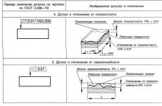
Theory of machines and mechanisms. Indication on the drawings of the tolerances of the shape and location of surfaces Limit deviations of the shape and location of surfaces
GOST 2.308 - 79
Deviations are necessarily indicated on technical drawings, indicating their symbolic designations, as well as full and short names. Symbols in such documentation are indicated using special graphic symbols.
Various symbols are necessary in order to indicate the tolerances for the location and shape of surfaces on the drawings.
Applying a variation on a drawingDeviations in the drawings are indicated using text entries in the margins, in places specially designed for this, as well as symbols.
Text entries are most often used in cases where the use of symbols threatens to lead to a "darkening" of the drawing, or in cases where only with their help it is possible to fully specify the technical requirements for the part.
Text entries include such mandatory elements as the short name of the deviation provided by the developers, as well as the name of the element or its letter designation. The values of limit deviations are nominated in millimeters. In those cases when deviations related to the relative position of the surfaces are marked, then the bases relative to which they are set are indicated without fail. These can be symmetry planes, common axes, lines, etc.
So that those tolerances that relate to the location of surfaces and deviations of shapes are not mixed with other tolerances, they are indicated in special rectangular frames connected by extension or other lines to contour lines of surfaces, axes of symmetry or dimension lines. In this case, the frames are divided into two or three parts, in the first of which the deviation symbol is indicated, in the second - its limit value, and in the third (if necessary) - the designation of the base surface.
Manufacturing errorsDeveloping technological processes with the help of which the manufacture of a particular product will be carried out, engineers solve a lot of various problems. One of them is to ensure the dimensions that will exactly match those indicated on the drawings, as well as the correct relative position of the surfaces of the workpieces and their proper shape.
Since the production errors of various machining operations accumulate during the manufacture of any part, their final value is subject to only an approximate estimate.
As you know, when performing various production operations on technological machine equipment, its individual parts are affected by cutting forces, which can reach (and usually reach) significant values and cause significant deformations.
The elastic system "machine - tool - part" in the process of operation can be subjected to significant vibration loads, which often lead to serious production errors. In addition, additional errors are formed due to the physical wear of individual parts of the processing equipment.
The wear of the cutting tool and the errors in its manufacture also significantly affect the final accuracy of machining parts. In this case, errors occur when a profile or measuring tool is used (reamers, countersinks, profile cutters, thread-cutting tools, etc.). The fact is that during processing, those deviations that its surfaces have are completely “copied” on the surfaces of the parts. In addition to these errors, there are many others.
Based on the foregoing, it can be stated that in real production conditions, the occurrence of surface errors of parts is an inevitable process.
Deviation of the location of the EP called the deviation of the real location of the element under consideration from its nominal location. Under nominal understood location determined by the nominal linear and angular dimensions.
To assess location accuracy surfaces are assigned bases (element of the part, in relation to which the location tolerance is set and the corresponding deviation is determined).
Location tolerance called the limit that limits the permissible value of the deviation of the location of the surfaces.
TP location tolerance field –region in space or a given plane, inside which there must be an adjacent element or axis, center, symmetry plane within the normalized area, width or
the diameter of which is determined by the tolerance value, and the location
relative to the bases - the nominal location of the element in question.
Table 2 - Examples of applying shape tolerances in the drawing

The standard established 7 types of deviations in the location of surfaces :
- from parallelism;
- from perpendicularity;
- tilt;
- from coaxiality;
- from symmetry;
- positional;
- from the intersection of the axes
Deviation from parallelism - distances between planes (axis and plane, straight lines in the plane, axes in space, etc.) within the normalized area.
Deviation from squareness - deviation of the angle between the planes (plane and axis, axes, etc.) from the right angle, expressed in linear units ∆, over the length of the normalized section.
tilt deviation - deviation of the angle between the planes (axes, straight lines, plane and axis, etc.), expressed in linear units ∆, over the length of the normalized section.
Deviation from symmetry - the largest distance ∆ between the plane (axis) of the considered element (or elements) and the plane of symmetry of the base element (or the common plane of symmetry of two or more elements) within the normalized area.
Misalignment – the largest distance ∆ between the axis of the considered surface of revolution and the axis of the base surface (or the axis of two or more surfaces) along the length of the normalized section.
Deviation from the intersection of the axes – the smallest distance ∆ between the nominally intersecting axes.
Positional deviation - the largest distance ∆ between the actual location of the element (center, axis or plane of symmetry) and its nominal location within the normalized area.
Types of tolerances, their designation and image in the drawings are shown in tables 3 and 4
Table 3 - Types of location tolerances

Table 4 - Examples of images of location tolerances in the drawings

Table 4 continued

Table 4 continued

Table 4 continued

Total tolerances and deviations of the shape and location of surfaces
The total deviation of the shape and location EU called deviation , which is the result of a joint manifestation of deviation the shape and deviation of the location of the considered surface or the considered profile relative to the bases.
The field of total tolerance of the form and location of the vehicle - This region in space or on a given surface, within which all points of a real surface or a real profile must be located within the normalized area. This field has a given nominal position relative to the bases.
There are the following types of total tolerances :
- surface runout rotation about the base axis is the result of the joint manifestation of the deviation from roundness profile of the considered section and its deviation from the center relative to the base axis; it is equal to the difference between the largest and smallest distances from the points of the real profile of the surface of revolution to the base axis in the section perpendicular to this axis (∆);
- end runout –difference ∆ of the largest and smallest distances from the points of the real profile of the end surface to the plane perpendicular to the base axis; is determined on a given diameter d or any (including the largest) diameter of the end surface;
- beating in a given direction –difference ∆ of the largest and smallest distances from the points of the real profile of the surface of revolution in the section of the considered surface by a cone, the axis of which coincides with the base axis, and the generatrix has a given direction, to the top of this cone;
- full radial runout –difference ∆ of the greatest R max and least R min distances from all points of the real surface within the normalized area L to the base axis;
- full end runout –difference ∆ of the largest and smallest distances from the points of the entire end surface to a plane perpendicular to the base axis;
- deviation of the form of a given profile - the largest deviation ∆ of the points of the real profile, determined along the normal to the normalized profile within the normalized section L;
- deviation of the shape of a given surface - the largest deviation ∆ of the points of the real surface from the nominal surface, determined along the normal to the nominal surface within the normalized area L 1 ,L 2
Types of tolerances, their designation and image in the drawings are shown in tables 5 and 6.
Table 5 - Types of total tolerances and their conditional image

Table 6 - Examples of images of total tolerances in the drawings

Table 6 continued

The shape and dimensions of signs, frames and images of bases are shown in Figure 11

Figure 11 - The shape and size of the characters, the frames of the image of the bases
E single system of design documentation
FORM TOLERANCE INSTRUCTIONS
AND SURFACE POSITIONS
|
Moscow |
Foreword
The goals, basic principles and basic procedure for carrying out work on interstate standardization are established by GOST 1.0-92 “Interstate standardization system. Basic Provisions” and GOST 1.2-2009 “Interstate Standardization System. Interstate standards, rules and recommendations for interstate standardization. Rules for the development, adoption, application, updating and cancellation "
About the standard
1. DEVELOPED by the Federal State Unitary Enterprise "All-Russian Research Institute for Standardization and Certification in Mechanical Engineering" (FSUE "VNIINMASH"), the Autonomous Non-Profit Organization "Research Center for CALS-Technologies" Applied Logistics "(ANO NRC CALS-Technologies "Applied Logistics") "")
2. INTRODUCED by the Federal Agency for Technical Regulation and Metrology
3. ADOPTED by the Interstate Council for Standardization, Metrology and Certification (Minutes of May 12, 2011 No. 39)
|
Short name of the country according to MK (ISO 3166) 004-97 |
Country code according to MK (ISO 3166) 004-97 |
Abbreviated name of the national standards body |
|
Azerbaijan |
Azstandard |
|
|
Armenia |
Ministry of Economy of the Republic of Armenia |
|
|
Belarus |
State Standard of the Republic of Belarus |
|
|
Kazakhstan |
State Standard of the Republic of Kazakhstan |
|
|
Kyrgyzstan |
Kyrgyzstandart |
|
|
Moldova |
Moldova-Standard |
|
|
Russian Federation |
Rosstandart |
|
|
Tajikistan |
Tajikstandart |
|
|
Uzbekistan |
Uzstandard |
|
|
Ukraine |
Gospotrebstandart of Ukraine |
4. By order of the Federal Agency for Technical Regulation and Metrology dated August 3, 2011 No. 211-st, the interstate standard GOST 2.308-2011 was put into effect as the national standard of the Russian Federation from January 1, 2012.
6. REPUBLICATION. January 2012
Information on the entry into force (termination) of this standard is published in the index of "National Standards".
Information about changes to this standard is published in the index "National Standards", and the text of the changes - in information signs "National standards". In case of revision or cancellation of this standard, the relevant information will be published in the information index "National Standards"
GOST 2.308-2011
INTERSTATE STANDARD
|
Unified system of design documentation FORM TOLERANCE INSTRUCTIONS Unified system of design documentation. Representation of limits of forms and surface lay-out on drawings |
Introduction date - 2012-01-01
1 area of use
This standard establishes rules for specifying tolerances for the shape and location of surfaces in graphic documents.for products from all industries.
2. Regulatory references
This standard uses normative references to the following interstate standards:
The shapes and sizes of signs are given in the appendix.
Examples of specifying tolerances for the shape and location of surfaces are given in the annex and ISO 1101.
Table 1
|
Tolerance type |
Sign |
|
|
Shape tolerance |
Straightness tolerance |
|
|
Flatness tolerance |
||
|
roundness tolerance |
||
|
Cylindrical tolerance |
||
|
Longitudinal section profile tolerance |
||
|
Location tolerance |
Parallelism tolerance |
|
|
Perpendicularity tolerance |
||
|
Tilt tolerance |
||
|
Alignment tolerance |
||
|
Symmetry tolerance |
||
|
Position tolerance |
||
|
Axis crossing tolerance |
||
|
Total shape and location tolerances |
Radial runout tolerance Runout tolerance Runout tolerance in a given direction |
|
|
Full radial runout tolerance Full axial runout tolerance |
||
|
Tolerance of the shape of a given profile |
||
|
Tolerance of the shape of a given surface |
||
|
Note - The total tolerances of the shape and location of surfaces for which separate graphic signs are not established are indicated by composite tolerance signs in the following sequence: location tolerance sign, shape tolerance sign. For example: The sign of the total tolerance of parallelism and flatness; The sign of the total tolerance of perpendicularity and flatness; The sign of the total tolerance of inclination and flatness. |
||
4.3. Tolerances of the shape and location of surfaces and their values in electronic models of products are indicated in the planes of designations and indications in accordance with GOST 2.052.
4.4. The numerical values of the tolerances of the shape and location of the surfaces are in accordance with GOST 24643.
4.5. Tolerances of the shape and location of surfaces may be indicated in text in the technical requirements, as a rule, if there is no sign of the type of tolerance.
4.6. When specifying the tolerance of the shape and location of surfaces in the technical requirements, the text should contain:
Type of tolerance;
An indication of the surface or other element for which the tolerance is set (for this, a letter designation or constructive name is used that defines the surface);
The numerical value of the tolerance in millimeters;
Indication of the bases relative to which the tolerance is set (for location tolerances and total shape and location tolerances);
An indication of dependent tolerances of form or location (as appropriate).
4.7. If it is necessary to normalize the shape and location tolerances that are not indicated in the graphic document by numerical values and are not limited by other shape and location tolerances indicated in the graphic document, the technical requirements should contain a general record of the unspecified shape and location tolerances with reference to GOST 30893.2.
For example:
“General shape and location tolerances - according to GOST 30893.2 - K” or “GOST 30893.2 - K” (K is the accuracy class of general shape and location tolerances according to GOST 30893.2).
5. Application of tolerance symbols
5.1. With a symbol, data on the tolerances of the shape and location of surfaces are indicated in a rectangular frame divided into two or more parts (see figures,), in which are placed:
In the first - a tolerance sign according to the table;
In the second - the numerical value of the tolerance in millimeters;
In the third and subsequent- the letter designation of the datum(s) or the letter designation of the surface to which the location tolerance is associated (see ; ).
Figure 2
5.2. Frames should be made with solid thin lines. The height of the numbers, letters and signs that fit into the frames must be equal to the font size of the dimensional numbers.
The graphic image of the frame is given in the appendix.
5.3. The frame is placed horizontally. In necessary cases, a vertical arrangement of the frame is allowed.
It is not allowed to cross the frame with any lines.
5.4. The frame is connected to the element to which the tolerance applies, with a solid thin line ending with an arrow (see figure).
Figure 3
The connecting line can be straight or broken, but the direction of the connecting line segment ending in an arrow must match the direction of the deviation measurement. The connecting line is taken away from the frame, as shown in the figure.
Figure 4
In necessary cases, it is allowed:
Draw a connecting line from the second (last) part of the frame (see figure A);
End the connecting line with an arrow and on the material side of the part (see figure b).
Figure 5
5.5. If the tolerance refers to a surface or its profile, then the frame is connected to the contour line of the surface or its continuation, while the connecting line should not be a continuation of the dimension line (see figures,).
Figure 7
5.6. If the tolerance refers to an axis or plane of symmetry, then the connecting line must be a continuation of the dimension line (see figures A And b). If there is not enough space, the arrow of the dimension line can be combined with the arrow of the connecting line (see figure V).
Figure 8
If the size of an element has already been specified once, then it is not indicated on other dimension lines of this element used to symbolize the tolerance of the shape and location. A dimension line without a dimension should be considered as an integral part of the shape or location tolerance symbol (see figure).
Figure 9
5.7. If the tolerance refers to the sides of the thread, then the frame is connected to the image in accordance with the figure A.
If the tolerance refers to the axis of the thread, then the frame is connected to the image in accordance with the figure b.
Figure 10
5.8. If the tolerance refers to a common axis (plane of symmetry) and it is clear from the drawing for which surfaces this axis (plane of symmetry) is common, then the frame is connected to the axis (plane of symmetry) (see figures A And b).
Figure 11
5.9. Before the numerical value of the tolerance should be indicated:
Symbol Æ if the circular or cylindrical tolerance field is indicated by the diameter (see figure A);
Symbol Rif a circular or cylindrical tolerance field is indicated by a radius (see figure b);
Symbol T, if the tolerances of symmetry, intersection of axes, the shape of a given profile and a given surface, as well as positional tolerances (for the case when the positional tolerance field is limited by two parallel lines or planes) are indicated in a diametrical expression (see figure V);
Symbol T/2 for the same types of tolerances, if they are indicated in radius expression (see figure G);
The word "sphere" and the symbolÆ or Rif the tolerance field is spherical (see figure d).
Figure 12
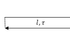
5.10. The numerical values of the tolerance of the shape and location of the surfaces indicated in the box (see figure A) refer to the entire length of the surface. If the tolerance refers to any part of the surface of a given length (or area), then the given length (or area) is indicated next to the tolerance and separated from it by an inclined line (see figures b And V), which must not touch the frame.
If it is necessary to assign a tolerance for the entire length of the surface and for a given length, then the tolerance for a given length is indicated under the tolerance for the entire length (see figures V, G).
Figure 13
5.11. If the tolerance must refer to a section located in a certain place of the element, then this section is indicated by a dash-dotted line and is limited in size according to the figure.
Figure 14
5.12. If it is necessary to set a protruding location tolerance field, then after the numerical value of the tolerance indicate the symbol .
The contour of the protruding part of the normalized element is limited by a thin solid line, and the length and location of the protruding tolerance field are limited by dimensions (see figure).
Figure 15
5.13. Inscriptions supplementing the data given in the tolerance frame should be applied above the frame, below it, or as shown in the figure.
Figure 16
5.14. If for one element it is necessary to set two different types of tolerance, then it is allowed to combine frames and arrange them according to the figure (upper designation).
If for a surface it is required to indicate both the shape or location tolerance symbol and its letter designation used to normalize another tolerance, then frames with both symbols can be placed side by side on the connecting line (see figure, bottom designation).
Figure 17
5.15. Repeating identical or different types of tolerances, denoted by the same sign, having the same numerical values \u200b\u200band referring to the same bases, are allowed to be indicated once in a frame from which one connecting line departs, which then branches to all normalized elements (see. drawing ).
Figure 18
5.16. The tolerances of the shape and location of symmetrically located elements on symmetrical parts are indicated once.
6. Designation of bases
6.1. The bases are indicated by a blackened triangle, which is connected with a connecting line to the frame. When executing a graphic document with the help of computer output devices, the triangle denoting the base is allowed not to be blackened.
The triangle denoting the base must be equilateral, with a height approximately equal to the font size of the dimension numbers.
6.2. If the base is a surface or its profile, then the base of the triangle is placed on the contour line of the surface (see figure A) or on its continuation (see figure b). In this case, the connecting line should not be a continuation of the dimension line.
Figure 19
6.3. If the base is an axis or plane of symmetry, then the triangle is placed at the end of the dimension line (see figure).
In case of lack of space, the arrow of the dimension line can be replaced with a triangle denoting the base (see figure).
Figure 20
If the base is a common axis (see figure A) or plane of symmetry (see figure b) and it is clear from the drawing for which surfaces the axis (plane of symmetry) is common, then the triangle is placed on the axis.
Figure 21
6.4. If the base is the axis of the center holes, then next to the designation of the base axis, the inscription "Axis of centers" is made (see figure).
Figure 22
It is allowed to designate the base axis of the center holes in accordance with the figure.
Figure 23
6.5. If the base is a certain part of the element, then it is indicated by a dash-dotted line and limited in size in accordance with the figure.
Figure 24
If the base is a certain place of the element, then it must be determined by the dimensions according to the figure.
Figure 25
6.6. If there is no need to select any of the surfaces as a base, then the triangle is replaced by an arrow (see figure).
Figure 27
6.8. If the size of an element has already been specified once, then it is not indicated on other dimension lines of this element used to symbolize the base. A dimension line without a dimension should be considered as an integral part of the base symbol (see figure).
Figure 29
6.10. If it is necessary to set the location tolerance relative to the set of bases, then the letter designations of the bases are indicated in independent parts (third and further) of the frame. In this case, the bases are written in descending order of the number of degrees of freedom they deprive (see figure).
Figure 32
8.2. If a location or shape tolerance is not specified as dependent, then it is considered independent.
Annex A
(reference)

Annex B
(reference)
Table B.1
|
Tolerance type |
Indication of shape and location tolerances by symbol |
Explanation |
|
1. Straightness tolerance |
Straightness tolerance of the generatrix of the cone - 0.01 mm |
|
|
|
Hole axis straightness tolerance -Æ 0.08 mm (tolerance dependent) |
|
|
|
Surface straightness tolerance 0.25 mm over the entire length and 0.1 mm - over a length of 100 mm |
|
|
|
Surface straightness tolerance in the transverse direction - 0.05 mm, in the longitudinal direction - 0.1 mm |
|
|
2. Flatness tolerance |
|
Surface flatness tolerance - 0.1 mm |
|
|
Surface flatness tolerance - 0.1 mm on an area of 100´ 100 mm |
|
|
|
Surface flatness tolerance relative to the common adjacent plane - 0.1 mm |
|
|
|
Flatness tolerance of each surface - 0.01 mm |
|
|
3. Roundness tolerance |
|
Shaft roundness tolerance - 0.02 mm |
|
Cone roundness tolerance - 0.02 mm |
||
|
4. Cylindrical tolerance |
|
Shaft cylindricity tolerance - 0.04 mm |
|
|
Shaft cylindricity tolerance - 0.01 mm over a length of 50 mm. Shaft roundness tolerance - 0.004 mm |
|
|
5. Tolerance of the profile of the longitudinal section |
|
Shaft roundness tolerance - 0.01 mm. Tolerance of the profile of the longitudinal section of the shaft - 0.016 mm |
|
|
Tolerance of the profile of the longitudinal section of the shaft - 0.1 mm |
|
|
6. Parallelism tolerance |
|
Tolerance of surface parallelism with respect to surface A- 0.02 mm |
|
|
Tolerance of parallelism of the common adjacent plane of surfaces relative to the surface A- 0.1 mm |
|
|
|
Tolerance of parallelism of each surface relative to the surface A- 0.1 mm |
|
|
|
Tolerance of parallelism of the hole axis relative to the base - 0.05 mm |
|
|
|
Tolerance of parallelism of the axes of the holes in the common plane - 0.1 mm. The skew tolerance of the axes of the holes is 0.2 mm. Base - hole axis A |
|
|
|
Tolerance of parallelism of the hole axis with respect to the hole axis A - Æ 0.2 mm |
|
|
7. Perpendicular tolerance |
|
Surface Perpendicularity Tolerance A- 0.02 mm |
|
|
Tolerance of perpendicularity of the hole axis relative to the hole axis A- 0.06 mm |
|
|
|
Perpendicularity tolerance of the protrusion axis relative to the surface A- Æ 0.02 mm |
|
|
|
Perpendicularity tolerance of the protrusion axis relative to the base - 0.1 mm |
|
|
|
Perpendicularity tolerance of the projection axis in the transverse direction - 0.2 mm, in the longitudinal direction - 0.1 mm. Base - base |
|
|
|
Tolerance of perpendicularity of the hole axis relative to the surface -Æ 0.1 mm (tolerance dependent) |
|
|
8. Tilt tolerance |
|
Tolerance of slope of the surface relative to the surface A- 0.08 mm |
|
|
Tolerance of inclination of the hole axis relative to the surface A- 0.08 mm |
|
|
9. Alignment tolerance |
|
Tolerance of alignment of the hole relative to the hole -Æ 0.08 mm |
|
|
Tolerance of alignment of two holes relative to their common axis -Æ 0.01 mm (tolerance dependent) |
|
|
10. Symmetry tolerance |
|
Groove symmetry tolerance - T 0.05 mm. A |
|
|
Hole symmetry tolerance - T 0.05 mm (tolerance dependent). Base - plane of symmetry of the surface A |
|
|
|
Tolerance of symmetry of the axis of the hole relative to the common plane of symmetry of the grooves AB - T 0.2 mm and relative to the common plane of symmetry of the grooves VG - T 0.1 mm |
|
|
11. Position tolerance |
|
Positional tolerance of the hole axis -Æ 0.06 mm |
|
|
Positional tolerance of hole axes -Æ 0.2 mm (tolerance dependent) |
|
|
|
Positional tolerance of axes of four holes -Æ 0.1 mm (tolerance dependent). Base - hole axis A(tolerance dependent) |
|
|
|
Positional tolerance of four holes -Æ 0.1 mm (tolerance dependent) |
|
|
|
Positional tolerance of three threaded holes -Æ 0.1 mm (tolerance dependent) in the area located outside the part and protruding 30 mm from the surface |
|
|
12. Tolerance of intersection of axes |
|
Tolerance of intersection of the axes of the holes - T 0.06mm |
|
13. Radial runout tolerance |
|
The tolerance of the radial runout of the shaft relative to the axis of the cone - 0.01 mm |
|
|
Tolerance of radial runout of the surface relative to the common axis of the surfacesA And B- 0.1 mm |
|
|
|
Tolerance of radial runout of a surface area relative to the axis of the hole A- 0.2 mm |
|
|
|
The tolerance of the radial runout of the hole is 0.01 mm. First base - surface A. Second base - surface axis B. End runout tolerance relative to the same bases - 0.016 mm |
|
|
14. Axial runout tolerance |
End runout tolerance at a diameter of 20 mm relative to the surface axis A- 0.1 mm |
|
|
15. Runout tolerance in a given direction |
|
Cone run-out tolerance relative to the hole axis A in the direction perpendicular to the generatrix of the cone - 0.01 mm |
|
16. Tolerance of full radial runout |
Tolerance of full radial runout relative to the common axis of the surfacesA And B- 0.1 mm |
|
|
17. Full axial runout tolerance |
|
Tolerance of full face runout of the surface relative to the axis of the surface - 0.1 mm |
|
18. Tolerance of the shape of a given profile |
|
Tolerance of the form of a given profile - 70.04 mm |
|
19. Tolerance of the shape of a given surface |
|
Tolerance of the shape of a given surface relative to surfaces A, B, IN- 70.1 mm |
|
20. Total parallelism and flatness tolerance |
|
The total tolerance of parallelism and flatness of the surface relative to the base - 0.1 mm |
|
21. Total tolerance of perpendicularity and flatness |
|
The total tolerance of perpendicularity and flatness of the surface relative to the base - 0.02 mm |
|
22. Total tilt and flatness tolerance |
|
The total tolerance of the slope and flatness of the surface relative to the base - 0.05 mm |
|
Notes 1. In the examples given, the tolerances of alignment, symmetry, positional, intersection of axes, the shape of a given profile and a given surface are indicated in diametric terms. It is allowed to specify them in a radius expression, for example: In previously issued documentation, the tolerances for alignment, symmetry, displacement of the axes from the nominal location (positional tolerance), indicated respectively by signs or text in the technical requirements, should be understood as tolerances in radius terms. 2. An indication of the tolerances of the shape and location of surfaces in text documents or in the technical requirements of a graphic document should be given by analogy with the text of the explanations for the symbols for shape and location tolerances given in this Appendix. At the same time, surfaces to which tolerances of shape and location belong or which are taken as a base should be indicated by letters or their design names should be given. It is allowed to indicate a sign instead of the words "dependent tolerance" and instead of indications before the numerical value of the symbolsÆ ; R; T; T/ 2 - text entry, for example, "positional tolerance of the axis is 0.1 mm in diametric terms" or "symmetry tolerance is 0.12 mm in radial terms." 3. In the newly developed documentation, the entry in the technical requirements for tolerances of ovality, cone shape, barrel shape and saddle shape should be, for example, the following: “Tolerance of ovality of the surface A 0.2 mm (semi-difference of diameters)". In the technical documentation developed before January 1, 1980, the limit values of ovality, cone shape, barrel shape and saddle shape are defined as the difference between the largest and smallest diameters. |
||


Deviations from the ideal geometric shapes and the ideal relative position of the surfaces of the part can violate its correct relative position relative to others and prevent the normal operation of the mechanism. For example, the end (axial) runout of the ledge, which fixes the rolling bearing in the axial direction, indicates a non-perpendicularity between the bearing plane of the ledge and the shaft axis and leads to a misalignment of the inner ring of the bearing relative to the outer one. Skewed keyway not only displaces the part mounted on the shaft, but can also interfere with assembly. Therefore, it is necessary to limit those deviations of geometric shapes and relative position that cause installation inaccuracies and malfunctions. Tolerances are set in accordance with the required accuracy of products and with the technical capabilities of the machines on which these products are processed. The shape and location tolerances are indicated on the working drawings according to the samples shown in fig. 28.29, symbols according to GOST 2.308-79. If necessary, the instructions are made in text in the technical requirements on the drawing. Different organizations assign shape and location tolerances differently. Only partially the rules for their selection are covered by the standards. In gearboxes, these tolerances are assigned to ensure satisfactory operation of rolling bearings and gears. For general purpose gearboxes on tapered roller bearings, it is possible, based on standards, literature data and experience gained at the VNIIreduktorostroenie, to adopt the following tolerances, shapes and locations. For the seat of the rolling bearing on the shaft (Fig. 28, a), the cylindricity tolerance is (0.3 ... 0.5) 7, where T is the diameter tolerance of the seat, the alignment tolerance (hereinafter - in diametric terms) relative to axes of the shaft centers - (0.7 ... 1.0) T. The perpendicularity tolerance between the axis of the centers and the plane of the shoulder fixing the inner ring of the bearing in the axial direction can be assigned the same (Fig. 28, b). For the seat of the gear wheel, the coupling on the shaft, the alignment tolerance relative to the axis of the centers (Fig. 28, c) is equal to the tolerance of the diameter of this seat. The pa position of the wheel with a hub shorter than 0.8d can be influenced by the shoulder of the shaft on which it rests. In this case, it is justified to assign a tolerance of perpendicularity of the plane Tolerance of surface cylindricity B 0.0 / mm Tolerance of surface coaxiality in relative to the axis of centers 0.015 mm Tolerance of perpendicularity of the surface D relative to the axis of the center 0.0 (5 mm surfaces A and b. groove d relative to the axis of the hole 0.20 mm The tolerance of the perpendicularity of the surface b relative to the axis will select and I 0.025 mm but in diameter / 50mm Positional tolerance of the hole B 0.bmm; Base axis of surface A (tolerance dependent) Tolerance of parallelism of surfaces a and B 0.025 mm Tolerance of coaxiality of surface C relative to the axis of surface D 0.04 mm Tolerance of parallelism of surfaces A and B 0.02 mm cularity u Tolerance of parallelism of the axes E and G 29. The tolerances of the shape and arrangement of the elements of the body parts of the shoulder to the axis of the centers are the same as the tolerance of the perpendicularity of the shoulder fixing the inner ring of the bearing. In the case of a longer hub, it is not necessary to specify the shoulder perpendicularity tolerance, because the position of the hub is determined mainly by the fit of its cylindrical interface with the shaft. For a gear wheel, the tolerance of the perpendicularity of the end of the hub to the axis of its central hole (Fig. 28, e) can be taken equal to 0.7 ... 1.0 tolerance of the 6th grade for the diameter of the hub. If the hub length is less than 0.8d, instead of the perpendicularity tolerance, the same parallelism tolerance between the ends of the hub should be assigned. For a keyway on the shaft and in the hub hole (Fig. 28, e), the tolerance of parallelism of the axis of the groove with respect to the axis of the centers of the shaft or the axis of the hole in the hub is 0.6 of the tolerance of the groove width, and the tolerance of the symmetry of the groove with respect to the same axis (in diametric terms) - 4 groove width tolerances. For an overhead flange cover of a bearing seat (Fig. 218, g), the parallelism tolerance of the working end surfaces adjacent to the end of the seat and to the outer ring of the bearing is equal to the tolerance of the 6th grade for the outer diameter of the flange. The alignment tolerance of the seating surfaces of the lid and the socket for the cuff is equal to the tolerance of the 7th grade for the diameter of the socket. On the flange of the cover, the positional tolerance of the displacement of the axis of the mounting hole from the nominal location should also be indicated (Fig. 28, h). This tolerance in diametric terms (twice the maximum displacement from the nominal location) Г = 0.4 (D-d), where D is the nominal diameter of the bolt hole; d is the nominal diameter of the bolt shaft. For the distance ring, the tolerance of the parallelism of the ends (Fig. 28, i) is 0.7 of the tolerance of the seat of the rolling bearing on the shaft. The technical characteristics of the gearbox indicate the minimum values of the lateral clearance (tab. 67) and the size of the contact patch. For the 7th degree of contact accuracy, the spot length must be at least 60% of the tooth length, the height - at least 45% of the tooth height. For body parts, the following shape and location tolerances are indicated (Fig. 29). The cylindricity tolerance of the seat of the outer stake of the bearing is 0.3 ... 0.5 of the tolerance of the diameter of this seat. The tolerance of the perpendicularity of the end face of the bearing housing to the axis of the seating surfaces can be calculated as follows. Let the seating surface diameter D = 100Н7, the corresponding diameter tolerance Т ~ = 0.035 mm, and the perpendicularity tolerance 7\ shall be set by the designer at the diameter Dt = 140 mm. Then Tg \u003d T-b- \u003d 0.035 \u003d 0.05 mm, Table 69. Parallelism tolerances of the working axes of the gear tracks on the working width of the gear dog or half-chevroia (i.ch GOST 1643-81, for the 7th degree of accuracy by contact) Width » b. mm: epdoig _ 40 100 160 950 AO 40 100 100 280 400 Tolerance T. µm 11 16 20 25 28 and the tolerance value 0.05/140 is written in the frame. The tolerance of parallelism to the axis of the seating surfaces of the outer rings of the low-speed shaft bearings relative to the bearing plane of the gearbox sole is taken equal to 0.001/?, where B is the distance between the ends of the bearing seats. The parallelism tolerance of the axes TV is indicated on the width B, having calculated it as follows: according to the table. 69 find the tolerance of parallelism T on the width b of the gear rim (half-chevron), and the tolerance The tolerance of misalignment of the axes is half that of the parallelism tolerance. Flatness tolerances of body parts, mm/mm, are: for the support plane of the sole - 0.05/100; for parting planes - 0.01/100. With a plane length L, the tolerances are 0.05 -w- and 0.01 j^-, respectively. The numbers found in this way are written in frames. Positional tolerances for the location of the axes of the mounting holes in the ends of the bearing seats, in the flanges connecting the gearbox housing with its cover, and in the bottom of the housing are calculated and recorded on the drawings in the same way as the tolerances for the location of holes in the seat cover, but for holes in the flanges of housing parts and in the soles of the bases are not indicated (Fig. 28, h and Fig. 29). It should be noted that on the shaft, the alignment tolerances of the seats of gears, couplings and other parts rotating with the shaft must be assigned relative to the axis of rotation of the shaft, i.e., relative to the common axis of the bearing seats (Fig. 28, d), and not relative to the axis of centers, which is the technological base. Shoulder perpendicularity tolerances must also be assigned relative to the same common axis. However, in the practice of gear building, I often indicate the listed tolerances! relative to the axis of centers in order to simplify control.