Power supply for television antenna repair. Antenna Power Supply
Quote: Chugunov
From the point of view of abnormal improvements to the CLIENTS, this option is unacceptable. And for myself, friends and relatives - the solution is excellent, practical and convenient.
That's just a "little trick" late for 20 years, and I haven’t seen such antennas for a long time, some satellite dishes.
From the point of view of reliability, the R2 nominal can be increased, or it can be set to no more than 0.1 W in order to trigger the fuse if that ...
However, I remember, there were imported TVs in which the chassis was energized, and the body of the antenna connector was connected through a capacitor, however, this is also irrelevant today.
Maybe the topic for the article and too small, but not all topics should be large. I like it.
What can I say - I agree with almost every word of this comment by Sergey. Everything is so, and I did it myself - a protective resistor for 100-120 Ohm 0.125 W (sometimes alternately 1-3.3 kOhm to adjust the amplifier mode), to the junction point of the choke and the resistor - another ceramic at 0.047-0.1 microfarads (if there is a lot of cable to the antenna, the braid is oxidized, weak reception, etc. - sometimes it helped to press the excitation), and for those who have a VCR or game console - a power-down toggle switch (there is mainly a trans-RF) - KZ). It worked. If something is wrong, the resistor burned out calmly and quickly, without loading BP TV (and already 0.25 MLA burned for a long time and strongly smelled).
Therefore, on the basis of practice, agree with
Quote: koan51
The resistor is needed at 20-30 ohms, with a resistance of 100 ohms on the amplifier voltage of about 10 volts, which reduces the gain.
I can not: with a short-circuit resistor of 20-30 ohms connected to a 12-volt bus, the load current of the PSU will abruptly increase by 0.6-0.4 A - this is an abnormal situation for a circuit with an almost constant and commensurate consumption current. And if no protection works, then most likely the choke (aka small-sized!) Will start burning not weakly, frightening this very client (relative, friend) on the way.
The idea is practically good for its time, how to do it, everyone decides for himself, but I will also tell you a little story: the parents of a friend stopped working on TV, went to watch. Included - the rules. raster without signal. "A craftsman who worked at a radio factory (in 76, on a forklift truck - auth.) Watched, soldered everything, but did not have enough time to finish it." "And what was soldered? - yes, some wiring." "Let's see, first check the antenna" - and wanted to pull it out. As he took it, he couldn’t work it out - there is a PHASE, and the connector is modern, metal. And the leash detached (these + 12V on the RF amplifier antenna, apparently fell out from under the back cover when the TV was closed), the peasant soldered to the input 220V pad - the terminals are large, you do not need to disassemble ... That's it
The vast majority of antennas for receiving television programs incorporates a signal amplifier. Like any electronic device, it requires power. The main feature is the use of an antenna cable for simultaneous transmission of a useful signal and supply voltage. This principle of catering antenna amplifier long accepted as the standard de facto by most manufacturers of antennas and amplifiers for them. This is due to the fact that the distance from the amplifier to the power source is large, but it does not require an additional cable to the power supply.
Purpose of the amplifier
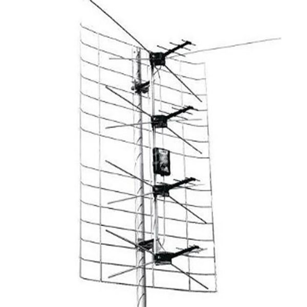
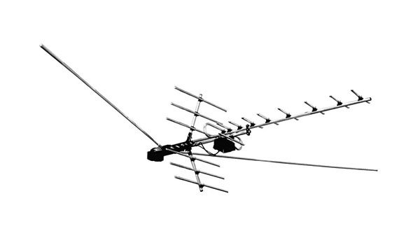
Confident reception of programs for viewing channels by terrestrial television with the help of a conventional antenna is possible only with a small distance from the transmitting center. In all other cases, the active antenna is supplemented with a receiving amplifier. As an example, Polish antennas, which have received the widest distribution, and Delta-type antennas can be cited.
The main function of a television antenna amplifier:
- increase the level of the useful signal to acceptable values;
- noise reduction.
The quality data is listed because the reception quality is affected not only by the magnitude of the useful signal, but also by its relation to the level of interference. For this reason, the antenna amplifier is in close proximity to the antenna, often entering directly into its design.
The supply voltage of the antenna amplifier is supplied through the antenna cable. To highlight the desired signal antenna, as Delta, so any other, is connected to the TV through the adapter. Some TVs or tuners have an antenna jack in which voltage is already present. Thus, the need for a power supply and adapter disappears, although it does not exclude the possibility of their use. To do this, in the TV settings menu there is always an item that allows you to turn off the power of the antenna through antenna input.
Important! Simultaneous power supply from the antenna jack and the external power supply unit is not allowed, as this may result in the failure of one or several devices. At best, the quality of reception will suffer.
Power supply parameters
An antenna amplifier requires a power supply with the following parameters:
- constant supply voltage from 9 to 12 volts;
- current value not more than 100 mA.
As a result, the power of the power device for a TV is units of Watts, so it can have very small dimensions.
Power supply device
In most cases, the power supply for television antenna consists of a step-down transformer with a bridge rectifier, a filter capacitor and an integral voltage regulator.
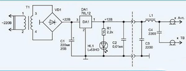
The output voltage of the transformer is about 12-18 V, preferably closer to the maximum value. Why so, will be discussed below. As a stabilizer, an integrated microcircuit of type 7812 is used. It is widely used due to successful parameters and is available with different permissible power. In this power supply, you can use a chip with a minimum power (the more powerful is quite acceptable, its dimensions are the criterion here). Domestic analogue 7805 - К142ЕН8Б (abbreviated name - КР ЕН8Б). For normal operation of the circuit, it is necessary that the voltage at its input exceeds the output voltage by at least two volts, and since the alternating voltage rises about 1.4 times after straightening and smoothing the capacitor, the minimum voltage at the output of the transformer is about 10 V. 12 V is selected taking into account possible reduction of the mains voltage.
The capacitance of the filter capacitor should provide smoothing voltage ripples. In this case, 220 microfarad is quite enough. The operating voltage of the capacitor should be several times higher than the rectified voltage, so it is better to take a capacitor rated for 35 V and higher. The LED serves to indicate the operation of the unit.
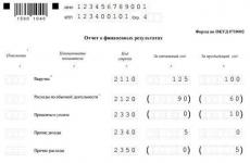
Very often, the antenna can receive both signals from a distant telecentre and a nearby one. In this case, it is possible that the antenna amplifier begins to self-excite, that is, to generate natural oscillations. A similar disadvantage is to a greater extent broadband antennas, which also includes the Delta antenna. The quality of reception while much worse. To overcome this situation, reduce the gain of the amplifier. This can be done by reducing the value of the supply voltage. This option is provided in the figure below.
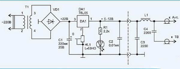
It can be seen that a variable resistor is included in the common output circuit (2) of the microcircuit. At the same time, the microcircuit itself has a different type - 7805 (the domestic analogue is К142ЕН5). With the minimum value of the resistance of the resistor, the stabilization voltage is equal to the passport value of the microcircuit - 5 V. By increasing the bias on the common pin, you can adjust the output voltage up to the input value.
High-quality regulated antenna power sources contain a stabilizer constructed using an adjustable integral stabilizer of the type LM317 (analogue - К142ЕН12). This variety is common, although the simplified scheme has proved itself well and has a lower cost.
Sometimes you can find an adjustable power supply, in which the resistor is simply included in the output conductor gap. This decision does not hold water and is characteristic only of cheap Chinese devices.
Connection
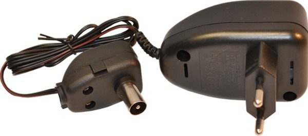
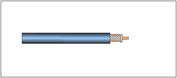
The industrial adapter for connecting to a TV is connected to the power supply unit with a two-wire cable and has two terminals for connecting the antenna cable. To connect the cable, you need to properly cut it. The cable, which will be connected to the antenna, consists of a central conductor enclosed in plastic insulation, and a shielding braid, which, in turn, is enclosed in insulation.
In order to connect the cable to the adapter, you must first carefully trim the outer insulation with a sharp knife at a distance of 2 cm from the edge, being careful not to cut the shielding conductors. Further isolation isolation from the cable. Stepping back 15 mm from the edge, cut off the screen. Remains central wire with insulation. Now stepping back from the screen by 1 mm, very carefully cut the central insulation to a depth of several millimeters. Having bent a cable several times in the place of the cut, it is necessary to ensure that the insulation bursts in a circle. Now it needs to be removed from the core.
Important! It is impossible to cut the insulation to the full depth, since the central core at the incision site will break.
The split cable is brought under the adapter terminals in such a way that the core falls under the fastening nut in the central terminal, and the shield braid lies under the wide terminal. You can now tighten the terminal screws. Connection is ready.
Note! At least one of the veins of the shielding braid should not be allowed to come into contact with the central terminal. The power supply will not fail (the chips have protection against short circuits), but the supply voltage to the antenna amplifier will not come.
Before you connect antenna cableIt is advisable to check the output voltage of the unit. Its values must be within the specified norm and in no case more.
Major faults
Amplifier power supplies rarely fail so that they cannot be repaired. The most often observed loss of capacitance of the filter. This fault manifests itself in the form of wave-like distortion of the image due to the penetration of voltage ripples on the amplifier and the antenna input of the TV. The reason is usually a low quality condenser. Externally, it will have a convex end (should be flat). For repair, it is enough to install a similar one with a capacity of 220-500 uF for a voltage of 35-50 V.
The lack of output voltage in the presence of a stabilizer chip at the input indicates a fault in the latter. For replacement, you can install any similar chip (analogs have been mentioned above).
In cases of power surges, the step-down transformer fails. Unfortunately, winding of windings will be necessary for its repair, which is difficult to implement at home. But if the transformer windings are made on separate coils, then there is the possibility not to resort to rewinding. Usually a fuse is built into the primary circuit. To get to it, you need to carefully, trying not to damage the conductors, cut off the external insulation of the primary winding, which is wound with a thin wire and has a large number of turns, and therefore much more secondary. The fuse is externally similar to a resistor and, in the event of a burnout, it has infinite resistance (the resistance of the healthy fuse is zero). A faulty fuse bridges a thin wire with a diameter of 0.05-0.07 mm.
The diode bridge is made on rectifying diodes with a large supply of voltage and current, so it almost never fails.
Much more often the junction of the cable and the adapter is loose, as a result of which the contact of the central conductor is lost, or it is short-circuited with the shielding braid. In this case, you need to properly and securely connect the antenna cable.
Summarizing, we can say that most consumers should not see the problem in how to properly connect the power supply and even repair it yourself. The most important thing is attentiveness, accuracy and desire.
Video
The vast majority have televisions, whether in black and white or in color. We all know that without a television antenna, there will be no image on the TV screen. During this time, our industry has manufactured a large number of television antennas of various designs.
But due to the collapse of the Union, the factories manufacturing antennas for television receivers simply stopped producing them. To replace our television products, they began to import. As our people say, a holy place is never empty. An opportunity to buy a good imported TV appeared in our markets, and, in addition, sellers also offered an imported multi-channel television antenna at a reasonable price.
Included antenna, included, antenna amplifier and power supply for it. Cable for the antenna had to be bought separately. He didn’t provide himself with the installation of the antenna that he had just bought on the market. For this it was necessary to have only a tool: a screwdriver, a penknife and a wrench.
After installing the TV antenna on a specially prepared platform, and turning on the TV, we tune it to the transmitting television center. Having tuned the TV in terms of image quality, we fix and fix the antenna so that it would not unfold during strong gusts of wind.
Recently, widespread reception of television channels has received, satellite television. Quality of the received television signal, from the satellite, in many respects exceeds the reception of a signal from an ordinary all-wave television antenna. Of course, not everyone can afford to buy a satellite dish, as we say, and therefore a simple but affordable all-wave antenna with an amplifier is in wide demand.
But here's one problem, she has during the operation, sometimes there are malfunctions, for one simple reason. During a thunderstorm, we forgot to turn off the power supply from the 220-volt power outlet, and at the same time tv cable with a plug from the antenna jack of the TV. As a result, the failure of the tuner, that is, the receiver of the TV or burn out a lot of expensive radio components.
My advice, do not forget to turn off during a thunderstorm television receiver and an antenna from an electrical network of 220 volts. So you save not only the TV, but also the antenna amplifier, and in addition your hard-earned money, which could be spent on repairing the TV.
Next we will have a story about repairing the power supply of the television amplifier. It consists of a power step-down transformer, a getinax board, four low-power silicon diodes, one electrolytic capacitor, a voltage stabilizer, and a signal LED.
Most often, an electrolytic capacitor fails in the power supply unit of the antenna amplifier. This fault is displayed on the TV screen in the form of broken lines, and most often you can observe how the black wide band is moving along the image. Immediately, without thinking twice, it is necessary to disassemble the power supply and replace the failed electrolytic capacitor with a capacity of 100 μF, 25 V. In rare cases, the voltage regulator itself fails, which outputs a stabilized constant voltage of 12 Volts for powering the antenna amplifier. The nature of the malfunction of the stabilizer is also displayed on the TV screen in the form of goosebumps or snow.
Who knows how to work with a soldering iron a little, it will not be difficult for him to replace the failed parts.
Good luck everyone